P:\INST-INS TRUCTIONS\CO NTROL CONSOLES \INST-TCC/RCC REV - 10/20 Page 2
Intentionally left blank
Страница 1: ...NTROL CONSOLES INST TCC RCC REV D 10 20 Page 1 Any suggestions or comments to this instruction or product are welcome Please contact us through our website or email engineer sdcsecurity com TCC RCC Se...
Страница 2: ...P INST INSTRUCTIONS CONTROL CONSOLES INST TCC RCC REV 10 20 Page 2 Intentionally left blank...
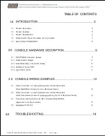
Страница 3: ...itch Outputs 2 1 2 Reset Button Key Lock Switch Output 2 1 3 LED Alarm Power 2 1 4 Control Inputs 3 0 3 1 Direct Connection to Locking Devices with 2 State Status LED Door Closed for AL or BL Series P...
Страница 4: ...P INST INSTRUCTIONS CONTROL CONSOLES INST TCC RCC REV 10 20 Page 4 Intentionally left blank...
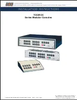
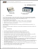
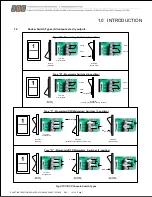
Страница 5: ...Series Consoles consist of an enclosure switches LEDs and terminal connector An audible alarm beeper is provided with E type switch panels containing the Alarm Shunt Reset Button and Key The Consoles...
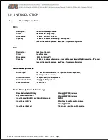
Страница 6: ...um when using 2 switch panels Base unit less switch panels See Page 6 for panel configurations Switch Panels All Models Switch Type Switch LED Count Rocker Switch Rating DRY Rocker Switch Output 2 or...
Страница 7: ...3 position Type D Momentary OFF Momentary Switches 3 position Closed Open Latched Open Closed Activated Latched until pressed back to Normal Normal Standby Terminal Configuration Terminal Configurati...
Страница 8: ...ion Part No Description Image AL4 Four Momentary Switches with LED s BL4 Four Maintained Switches with LED s CL4 Four Momentary Off Maintained Switches with LED s DL4 Four Momentary Off Momentary Swit...
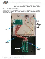
Страница 9: ...boards the numbers the switch Fig 3 TCC Interior View TCC x AL4 x EA shown Reset Switch Pre wired Switches Knockout for Field wiring Audible Shunt Key Lock Switch Reset Audible Shunt and Key Lock onl...
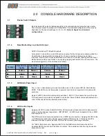
Страница 10: ...J8 Reset Button or Key Switch one per I O board J9 Audible Shunt Switch Note When using multiple I O boards the audible shunt switch may plug into any J9 connector To utilize both the reset button an...
Страница 11: ...d Terminal Reset Button Inactive Reset Button Pressed Key Lock Switch Key Horizontal Key Lock Switch Key Vertical A1 A2 A3 Common Closed Open Common Open Closed Common Closed Open Common Open Closed 2...
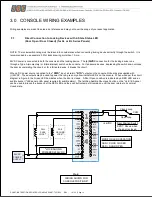
Страница 12: ...y completing the circuit or for a fail safe device it breaks the circuit When a DC power source is applied to the PWR input all return RTN outputs on the console I O boards are supplied with 24VDC The...
Страница 13: ...C These outputs may be used to power the red green or yellow indicator LED s on the console When wired per the circuit diagram in Figure 7 the amber LED illuminates while the door is unlocked opened b...
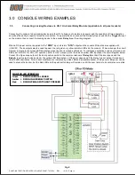
Страница 14: ...am in Figure 8 the Green LED illuminates when the door is closed and locked To indicate an authorized unlock or forced door status set the UR 1 for CR or TD operation refer to UR 1 manual wire the red...
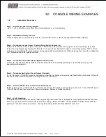
Страница 15: ...erminate the Door Monitoring Optional LED Inputs Connect the Door Position Status switches Latch Status switches to the LED inputs directly or via secondary relays per the appropriate wiring diagram S...
Страница 16: ...check the RCC TCC I O board for loose connections by carefully on all screw terminal connections Check wiring at door for switch continuity and or voltage If connected to doors via external relay modu...