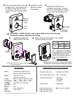
Install the Keypad and
Battery pack to the door
Carefully route all the wires
from the keypad thru the
battery pack backplate
a. Connect the 4-wire privacy cable to the back of the
privacy board.
b. Attach wires from the lockset to the keypad using the
charts below.
Additional Wire Connections from Keypad (Optional)
Door Position Switch Input
Auxiliary Relay Output
Factory Reset
= GRY / BLK(COM)
= ORG (N/C)
WHT(COM)
YEL(N/O)
= BRN / BRN
8
9
10
From
Keypad
From
Lockset
RED
WHT
RED
WHT
Function
Motor
Output
+
_
NOTE: Use E75-TOOL to
remove back cover to replace
batteries.
Steps 8-10 for E75KL and E75PL Privacy models only,
P:\INSTALLATION INST\ACCESS CONTROLS\E75\INST-E75.vsd REV F 03-20 Page 2
12VDC External Power
(NOTE: Ext. pwr harness
ships separately in box)
= RED(+) / BLK(-) (22AWG)
Gasket
Apply power by plugging in
the keypad’s 2-wire connector to
the battery pack connector. The
left LED will flash rapidly as
shown below followed by 3 beeps.
4-wire
Privacy
connector
2-wire
keypad
power
connector
Batter pack backplate
w/ privacy board
From
Keypad
From
Lockset
BLUE
BLACK
WHT/RED
YEL/RED
Function
Privacy
Reset
Replace the cover over the
battery pack by first hooking the
top and gently pressing the
bottom, ensuring that the privacy
button and LED are properly
aligned with the cover holes.


