Page 4 - Astra 100RS
Страница 1: ...ASTRA 100RS AUTOMATIC MANUAL TRANSMISSION REMOTE START SYSTEM PRODUCT MANUAL...
Страница 2: ...ear if required for repair and or replacement of any defective parts A copy of the original purchase and installation receipt must accompany any products returned for warranty service Warranty is limi...
Страница 3: ...Timer Feature Page 6 6 System Installation Page 7 Mounting the Control unit Page 7 7 System Wiring Page 8 5 Pin Starter Harness Page 8 16 Pin Main Harness Page 8 Plug in Connectors Page 9 8 Starter D...
Страница 4: ...Page 4 Astra 100RS...
Страница 5: ...n or there is adequate ventilation Failure to observe this rule could result in injury or death from poisonous CarbonTo ensure the safety and security of the system while it is remote started the Astr...
Страница 6: ...ot programmed within the following sequence Be sure to have all exixting remotes for programming To program 1 way transmitter s 1 Turn the ignition key On Off On Off and back On The parking lights wil...
Страница 7: ...hen the battery needs replacing the system s operating range will decrease or the transmitter LED may not be as bright In order to change the battery first remove the screw from the back of the transm...
Страница 8: ...se the door the system will shut the engine Off Starter is now ready for remote start operation Starter Ready Mode is canceled any time the door is opened hand brake is released or any other error con...
Страница 9: ...brake pedal to disengage the remote start feature and drive the vehicle Shut Down When the the Remote Start feature is active any of the following actions will shutdown the engine 1 Pressing the Butt...
Страница 10: ...o activate the Turbo Timer feature 1 Leave the engine running after parking the vehicle 2 Set the vehicle s parking brake The Turbo Timer will begin a two minute run cycle to allow the turbocharger to...
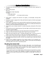
Страница 11: ...ircuits Never use a test light 10 Always look before drilling any holes or mounting self tapping screws Be sure fuel lines and exterior wiring looms are clear as they are often close to the chassis an...
Страница 12: ...ally found on Ford vehicles Pin 6 YELLOW WIRE 12V Ignition Input The Yellow wire must connect to a main ignition wire at the ignition harness This wire must show 12V when the ignition is on and while...
Страница 13: ...nput Connect to a constant source of 12V 2 Pin Blue Connector Valet switch port Mount switch where it is accessible from the driver s position 2 Pin Red Connector LED port Mount LED where it may be ea...
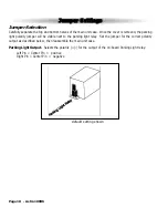
Страница 14: ...arity jumper will be visible next to the parking light relay Set the jumper for the correct polarity output as described below then reassemble the main unit case Parking Light Output Selects the polar...
Страница 15: ...Reset Following this procedure will set all System Programming Parameters to factory default settings 1 Enter System Programming 2 Press the Brake Pedal three times The parking lights will flash 6 tim...
Страница 16: ...ch 13 the LED should be flashing to indicate tach signal is present Press the Brake pedal 1 time to learn the vehicle s tach signal The LED will stop flashing to confirm learning of the tach signal Th...
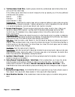
Страница 17: ...ime 15 minutes 25 minutes 11 Reserved N A N A N A 12 Tachless Sense Crank Time Normal Extended Super Extended 13 Engine Type RPM Mode RPM Learn Gas Engine Diesel Engine 14 Ignition 2 Output Program Ig...
Страница 18: ...Page 14 Astra 100RS Relay Diagrams Cont Negative Glow Plug...
Страница 19: ...es Operation is subject to the following two conditions 1 This device may not cause harmful interference 2 This device must accept any interference received including interference that may cause undes...
Страница 20: ...olet Starter Output Brown Ignition 2 Output Red 12V to Relays Blue Remote Start Input Black Gray Tach Input White Red Parking Brake Input Green Negative Door Input Violet Positive Door Input Yellow 12...