background image

Page 23

Page 23

consequently to the compressor and fan motors
and 30" later, to the water pump motors.
Then, as the ice thickness reaches the value that
corresponds to the full cube size, the film of water
that constantly cascades over the slab of ice
formed on the evaporator, arrives to establish a
contact between the two fingers (energised at
low voltage) of the ice sensor control, located on
the front upper right side of the evaporator. If the
contact between the two fingers of the ice sensor
remains established - by the film of water - for
more than 10 seconds, a small relay of the
electronic board, get energized, controlling -
simultaneously the hot gas valve,  the water drain
valve and the harvest assist solenoid.

NOTE: in case of failure of ice level sensor,
the P.C. Board turns - on automatically the
unit into the defrost cycle when the freezing
cycle reaches 30 or 40 minutes according to
the operation of the fan motor during the
freezing cycle.

At this point, the unit initiates the defrost cycle.
The hot gas circulating into the evaporator
serpentine causes a slight melting of ice cubes
which get released from their molds. In the mean
time the harvest assist solenoid is also energized
pushing out the ice plate.
Once entirely released the ice cubes drop
simultaneously into the ice storage bin below; by
doing so they move apart from the evaporator
bottom end the plastic deflector.
This plastic deflector has on its side a magnetic
switch that on account of the deflector swinging
motion, caused by the ice while dropping in the
bin, opens and closes their contacts.
This will, in turn, disactivate the relay contacts
that controls the hot gas, harvest assist solenoid
and water drain valve which get deenergized
allowing the unit to start a new freezing cycle.

When the ice bin is full of ice, the last batch of ice
cubes released from the evaporator accumulates
to keep the bottom end of the plastic deflector in
open position; with the magnetic switch contacts
open for longer than 30'’ the entire unit stops with
the glowing of the corresponding LED.
The machine will restart when the ice deflector will
be back in its normal vertical position provided
that 3' are elapsed from unit stop. If not the
machine will delay its restart till 3' are elapsed with
the blinking of the green LED.

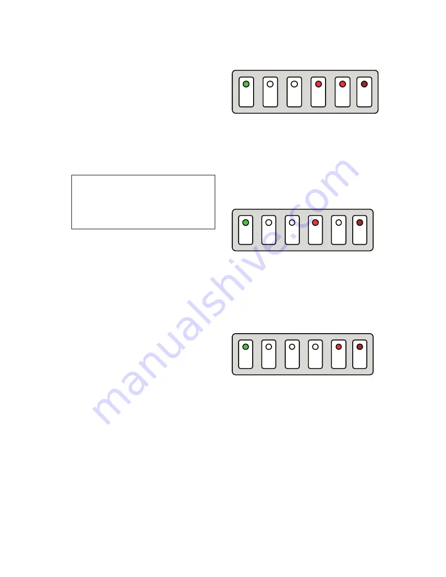
ALARM CONDITIONS

Both the last two Red LED are ON STEADY:
Condenser Sensor OUT OF ORDER.

Both the last two Red LED are BLINKING SLOW:
WATER ERROR

Water level inside the water sump too low after 3'
from the activation of the Water Inlet Valve.

Both the last two Red LED are BLINKING FAST:
RESET MODE: Charging water through the Water
inlet Solenoid Valve after the tripping OFF on
WATER ERROR

The fourth Red LED is ON STEADY: Harvest
Cycle longer then 3' 30"

The fourth Red LED is BLINKING SLOW: TOO HI
CONDENSING TEMPERATURE. 
The condenser
sensor detected a temperature > 65

°

C

The fourth Red LED is BLINKING FAST:
RESET MODE: Condenser Sensor < 50

°

C Fan

motor in operation for 3' then back on Start Up
Cycle Mode

The fifth Red LED is ON STEADY: TOO HI
DISCHARGE PRESSURE > 33 bar (460 PSI)

The fifth Red LED is BLINKING FAST:
RESET MODE: After pushing the Reset
Button of the Pressure Control the fan motor
starts up first for 3' then the machine enters
on the Start Up Cycle Mode.

The PC Board is also checking the maximum
time of the freezing cycle that changes according
to the operation of the fan motor during the
freezing cycle (room temperature):

• Fan motor in

Max. freezing cycle length

  ON-OFF mode:

equal to 30'

• Fan motor ON

Max. freezing cycle length

  All the time:

equal to 40'

Whenever the machine remains in the Freezing
Cycle for the Maximum time (30 or 40 minutes),
the PC Board moves the unit directly into the
Harvest Cycle.

POWER

OPER.

BIN

FULL

ALARM

ALARM

HI

PRESS.

RE-SET

POWER

OPER.

BIN

FULL

ALARM

ALARM

HI

PRESS.

RE-SET

POWER

OPER.

BIN

FULL

ALARM

ALARM

HI

PRESS.

RE-SET

Содержание MV 1006

Страница 1: ...93960 1 Aut Sel Telefax 39 02 93550500 Direct Line to Service Parts Phone 39 02 93960350 Fax 39 02 93540449 Website www scotsman ice com E Mail scotsman europe frimont it ISO 9001 Cert n 0080 SERVICE...

Страница 2: ...e 18 Freezing cycle 18 Harvest cycle 18 OPERATION Refrigeration during freeze 20 Water system during freeze 21 Refrigeration system during harvest 22 Water system during harvest 22 Control sequence 22...

Страница 3: ...ance as outlined on the last pages of this manual ice making capacity ICE PRODUCED PER 24 HRS Kg 32 C 15 10 AIR COOLED MODELS WATER TEMPERATURE AMBIENT TEMPERATURE C 10 21 32 38 WATER COOLED MODELS 21...

Страница 4: ...rt amps watts Electric power cons Kwhx24 HR N of wires Amps Fuse 220 240 50 1 MV 306 AS MV 306 WS 3x1 5 mm2 10 Cubes per harvest 168 Full 336 Half With water at 15 C Stainless Steel 3 4 3 8 3 3 20 780...

Страница 5: ...e as outlined on the last pages of this manual ice making capacity ICE PRODUCED PER 24 HRS K g 32 C 10 AIR COOLED MODELS WATER TEMPERATURE AMBIENT TEMPERATURE C 10 21 32 38 WATER COOLED MODELS 240 220...

Страница 6: ...NS Water req lt 24 HR Model Basic electr amps Start amps watts Electric power cons Kwhx24 HR N of wires Amps Fuse 220 240 50 1 MV 426 AS MV 426 WS 3x1 5 mm2 16 Cubes per harvest 204 Full 408 Half With...

Страница 7: ...intenance as outlined on the last pages of this manual ice making capacity ICE PRODUCED PER 24 HRS Kg 32 C 15 10 AIR COOLED MODELS WATER TEMPERATURE AMBIENT TEMPERATURE C 10 21 32 38 WATER COOLED MODE...

Страница 8: ...Start amps watts Electric power cons Kwhx24 HR N of wires Amps Fuse 220 240 50 1 MV 456 AS MV 456 WS 3x1 5 mm2 16 Cubes per harvest 234 Full 468 Half With water at 15 C Stainless Steel 7 8 MV 456 AS...

Страница 9: ...nance as outlined on the last pages of this manual ice making capacity Kg 32 C 15 10 C 10 21 32 38 21 335 315 295 275 255 235 215 195 175 Kg 32 C 15 10 C 10 21 32 38 21 335 315 295 275 255 235 215 ICE...

Страница 10: ...ter req lt 24 HR Model Basic electr amps Start amps watts Electric power cons Kwhx24 HR N of wires Amps Fuse 220 240 50 1 MV 606 AS MV 606 WS 3x1 5 mm2 16 Cubes per harvest 234 Full 468 Half With wate...

Страница 11: ...as outlined on the last pages of this manual ice making capacity Kg 32 C 15 10 C 10 21 32 38 21 445 425 405 385 365 345 325 305 285 265 245 225 Kg 32 C 15 10 C 10 21 32 38 21 390 370 350 330 310 290...

Страница 12: ...er req lt 24 HR Model Basic electr amps Start amps watts Electric power cons Kwhx24 HR N of wires Amps Fuse MV 806 AS MV 806 WS 3x1 5 mm2 16 Cubes per harvest 342 Full 684 Half With water at 15 C Stai...

Страница 13: ...nce as outlined on the last pages of this manual ice making capacity Kg 32 C 15 10 C 10 21 32 38 21 475 455 435 415 395 375 355 335 315 295 275 Kg 32 C 15 10 C 10 21 32 38 21 425 405 385 365 345 325 3...

Страница 14: ...amps Start amps watts Electric power cons Kwhx24 HR N of wires Amps Fuse Cubes per harvest 342 Full 684 Half With water at 15 C Stainless Steel 2 Dimensions HEIGHT 725 mm 28 1 2 WIDTH 760 mm 30 DEPTH...

Страница 15: ...k on top of Scotsman bin model B 193 the MV 456 606 806 1006 stack onto SCOTSMAN bin model B 393 Refrigerant R 404 A Charge per nameplate rating STANDARD LEGS Furnished with storage bin Fourlegsscrewi...

Страница 16: ...hatthenecessaryutilitiesareavailableincluding the correct voltage electrical power thattherebespacearoundtheinstalledmachine for service 15 cm minimum left right and rear for air cooled models STORAGE...

Страница 17: ...water supply for the MV Cuber consideration should be given to A Length of run B Water clarity and purity C Adequate water supply pressures Sincewateristhemostimportantsingleingredient in producing ic...

Страница 18: ...w seconds to re fill the water reservoir up to the maximum level so to reduce any possibility of slush ice formation 6 Inthemeantimethecondensersensorstarts to transmit the current to the PC Board kee...

Страница 19: ...nutes delay time 8 Place again all cabinet panels and screws previously removed 9 Thoroughlyexplaintoowner userthesignificant specifications of the ice maker start up reset and operation going through...

Страница 20: ...h liquid refrigerant is to be allowed into the evaporator section of the refrigeration system This is determined by the temperature of the TXV sensing bulb located on the suction line manifold at the...

Страница 21: ...rvoir to be sucked back into the pump and repumped over the evaporator WATER SYSTEM A combination of a solenoid water inlet valve with a water level sensor is used to control the level of the water in...

Страница 22: ...r is drawn into the suction tube of the compressor WATER SYSTEM During the harvest cycle the electric water drain valve is energized thereby opening the drain line Most of the water remained in the re...

Страница 23: ...ce cubesreleasedfromtheevaporatoraccumulates to keep the bottom end of the plastic deflector in open position with the magnetic switch contacts open for longer than 30 the entire unit stops with the g...

Страница 24: ...time only at beginning of every harvest cycle Suggested for soft water JUMP IN J2 Manual reset mode and water purge out for a short time only at beginning of every harvest cycle plus a full water purg...

Страница 25: ...0 1200 Refrigerant metering device Thermostatic expansion valve SERVICE SPECIFICATION In servicing a machine it is often useful to compare that individual units operating characteristics to those of a...

Страница 26: ...ived back from the Ice Tickness Sensor according to the Electrical Conductivity of the water 3 Compressor Contactor Located in the control box the compressor contactor functions to carry the compresso...

Страница 27: ...motor so to cool the condenser and to reduce its temperature In case the condenser temperature rises and reaches 65 C 150 F the current arriving to the micro processor is such to cause an immediate an...

Страница 28: ...the vertical tygon tube to the water distributors above the evaporator plate and from the holes in the distributor tube water flows to the cells on one side of the evaporator plate Gravity flow return...

Страница 29: ...ough the water When the current reaches the PC Board the water inlet solenoid valve is de energised In case the PC Board doesn t receive any signal current from the Water Level Sensor within the first...

Страница 30: ...G Condenser temperature probe H Led card I PC Board J Hi pressure switch K Manual Automatic reset jumper L Water pump M Water inlet valve N Water drain purge valve O Hot gas valve P Fan Motor only AIR...

Страница 31: ...nic card J Max pressure switch K Automatic reset switch L Water pump M Water inlet valve N Water discharge valve O Hot gas valve SP Solenoid harv assist P1 Fan Motor only AIR cooled unit P2 Fan Motor...

Страница 32: ...ssure switch K Automatic reset switch L Water pump M Water inlet valve N Water discharge valve O Hot gas valve SP Solenoid harv assist P1 Fan Motor 1 only AIR cooled unit P2 Fan Motor 2 only WATER coo...

Страница 33: ...P C Board open Machine runs makes Low refrigerant charge Checksystemforcorrectrefr charge and harvests ice Check for leak weight in charge but very slowly Low ice capacity High discharge pressure Evac...

Страница 34: ...HoldingtheevaporatordeflectorinopenPosition for more that 30 shold cause the ice maker to shut off Once the evaporator deflector is released in its closed position the ice maker will restart 8 Check...

Страница 35: ...d any possible trace of Ice Machine Cleaner 6 At the end of the 7th Rinsing cycle the P C Board stops the operation of the machine with the blinking slow of the Yellow LED 7 Pushing the RESET BUTTON f...

Отзывы: