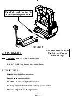
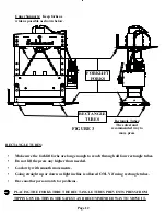
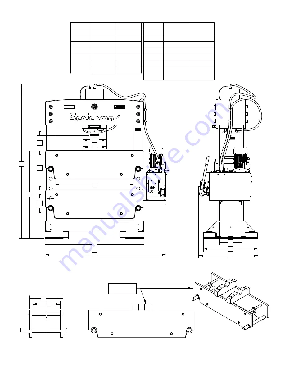
Scotchman PRESSPRO 110 Скачать руководство пользователя страница 9

FIGURE 1

Page 8

M

L

PLACE V-BLOCKS

OR TABLE HERE

PRESSPRO

110 TON

H

I

A

E
C

J

D

B

F

CROSS BEAM ASSY.

TOP POSITION

CROSS BEAM ASSY.
BOTTOM POSITION

G

O

N

K

A
B

C

D
E
F

G

H

J
K

MM

I

UNITS INCHES

L
M

MM

UNITS INCHES

N

O

84-3/4

2153

54-1/4

1378

30

762

43-1/4

1099

12-1/8

308

66-1/2

1689

137

5-3/8

8-11/16

221

21-1/2

546

32-3/4

832

4-3/4

121

16-5/16

414
364

14-5/16

343

13-1/2

1219

48

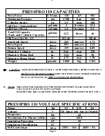
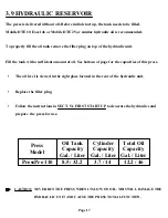
PRESSPRO 110 SPECIFICATIONS

Содержание PRESSPRO 110

Страница 1: ...You have downloaded a manual for the SCOTCHMAN PRESSPRO 110 HYDRAULIC PRESS...

Страница 2: ...www scotchman com PRINTED DECEMBER 2022 PRESSPRO 110 HYDRAULIC PRESS SCOTCHMAN INDS 180 E US HWY 14 PO BOX 850 PHILIP SD 57567 Phone 1 800 843 8844 www scotchman com S N 2000 and higher...

Страница 3: ...Page 2 PRESSPRO 110 SCOTCHMAN INDS 180 E US HWY 14 PO BOX 850 PHILIP SD 57567 Phone 1 800 843 8844 www scotchman com...

Страница 4: ...Control Valve Oil Filler Plug Speed Setting Valve MACHINE START UP AND OPERATION First Start Up Positioning The Press Cylinder Positioning The Table OPERATING THE PRESSPRO 110 V Block Set PRESSPRO 110...

Страница 5: ...ller s option returns the defective goods freight and delivery prepaid to the seller which shall be the buyer s sole and exclusive remedy for defective goods Hydraulic and electrical components are su...

Страница 6: ...operator must be aware of the capacities of the machine and its proper use This manual is not intended to teach untrained personnel how to operate machinery 2 All of the guards adjustable restrictors...

Страница 7: ...R TURN OFF THE MACHINE WHEN PRESSING FORCE IS BEING APPLIED TO THE WORK PIECE UNEXPECTED FORCE EXPANSION WHEN RESTARTING CAN DAMAGE THE MACHINE OR INJURE THE OPERATOR THEREFORE ALWAYS RELEASE THE FORC...

Страница 8: ...chman PressPro 110 press UPON DELIVERY DO NOT SIGN FOR ANY MACHINE UNTIL YOU HAVE REMOVED THE PLASTIC AND INSPECTED EVERYTHING FOR DAMAGE It is the customer s responsibility to inspect the arriving ma...

Страница 9: ...POSITION CROSS BEAM ASSY BOTTOM POSITION G O N K A B C D E F G H J K MM I UNITS INCHES L M MM UNITS INCHES N O 84 3 4 2153 54 1 4 1378 30 762 43 1 4 1099 12 1 8 308 66 1 2 1689 137 5 3 8 8 11 16 221...

Страница 10: ...e See Pg 13 Press Speed Return Speed Weight Diameter Cylinder Diameter Piston Rod Diameter Piston Head US tons psi in gal min gallons in sec pounds in in in in sec in sec gal min Approach Speed Oil Fl...

Страница 11: ...ck you use has enough capacity to safely lift the weight the press and follow the instructions below 3 3 PALLET JACK CAUTION Use extreme caution when moving press as it is TOP HEAVY When moving the pr...

Страница 12: ...ORKLIFT CAUTION PRESS IS VERY TOP HEAVY Refer to FIGURE 3 on the next page for the below Page 11 UPPER SUPPORTS Place the table in its lowest position Keep forks as wide as possible Do not lift the pr...

Страница 13: ...CTANGLE TUBES PREVENTS PRESS FROM TIPPING OVER THIS IS THE SAFEST AND RECOMMENDED WAY TO MOVE IT RECTANGLE TUBES Make sure the forklift forks are long enough to reach through all four rectangle tubes...

Страница 14: ...ressPro 110 has six holes available in the base for this three on each side FIGURE 4 below is a view of the underside of the machine showing the location of these holes They are on the inside of the b...

Страница 15: ...hey need to be installed so the longer part is pointing to the outside of the machine as shown on the next page in FIGURE 5 Each bracket should be bolted to a leg with two bolts and two washers 3 6 MO...

Страница 16: ...ashers as shown below 3 7 INSTALLATION OF THE HYDRAULIC UNIT NOTE THE HYDRAULIC UNIT WEIGHS 130 LBS WHEN PLACING THE UNIT IN THE CORRECT POSITION MAKE SURE TO USE ENOUGH MAN OR MACHINE POWER TO LIFT T...

Страница 17: ...E TIGHTENED SECURELY AND CONNECTED IN THE CORRECT LOCATION BEFORE FILLING RESERVOIR AND OPERATING THE PRESS FRONT BACK A C HANDLE AND SCREW REMOVED HANDLE INSTALLED IN CORRECT ORIENTATION PLACE HOSE M...

Страница 18: ...tank needs to be filled Mobile DTE 10 Excel 46 or Mobile DTE 25 or similar hydraulic oil is recommended To properly fill the oil tank remove the filler plug on top of the hydraulic unit Fill the tank...

Страница 19: ...circuit must be protected by a fuse or circuit breaker with an adequate rating The motor direction can be changed by swapping 2 of the incoming phases See SECT 3 11 The motor must be running in corre...

Страница 20: ...TIC L3 L2 L1 T1 T3 MTR 1M 1OL T2 INCOMING SUPPLY BY CUSTOMER PROVIDE MAXIMUM UPSTREAM PROTECTION PER N E C CODE 430 52 AND TABLE 430 152 GND 95 96 1OL E STOP 1 2 1PB START 3 4 2PB A2 1M A1 1M 13 14 L1...

Страница 21: ...T BUTTON 6 5 8 6 5 5 7 Brown Black Blue Follow Instruction Sheet In Motor Box If Provided Brown TO MOTOR SET OVERLOAD TO FLA SHOWN ON SERIAL NO PLATE W2 U2 V2 U1 V1 W1 W2 U2 V2 U1 V1 W1 NOTE Swap 2 In...

Страница 22: ...ACHINE CONTROLS 2 Speed Low Speed HL46 Pressure Piston EMERGENCY STOP E M E R G E N C Y S T O P TOP VIEW HYDRAULIC UNIT FRONT VIEW ON OFF SWITCH 1 ON OFF SWITCH 2 EMERGENCY STOP BUTTON 3 PRESSURE CONT...

Страница 23: ...PPLIED TO THE WORK PIECE UNEXPECTED FORCE EXPANSION WHEN RESTARTING CAN DAMAGE THE MACHINE OR INJURE THE OPERATOR 4 2 EMERGENCY STOP BUTTON 2 The emergency stop button is located on top of the on off...

Страница 24: ...plug is clean before adding oil 5 The speed setting valve handle is located on top of the hydraulic unit on the upper right The PressPro ram can move at two different speeds The faster speed allows th...

Страница 25: ...s As long as the valve is pulled rearward the press ram will move When the lever is released the press ram will stop and stay in this position If the press ram reaches its lowest position end of the c...

Страница 26: ...per position Start hydraulic unit Using the directional control valve joy stick move the ram down 3 4 inches then bring the ram back to its upper position Repeat this complete cycle until the ram has...

Страница 27: ...not completely remove the levers Move the complete cylinder to the left or right by means of the bow grip handle When the cylinder is in the desired position tighten the levers Manual tightening is e...

Страница 28: ...am upwards in the low speed position of the speed setting valve The table will be lifted up and off the blocking pins TO LOWER THE TABLE When table is lifted off the blocking pins take out both blocki...

Страница 29: ...E ON THE RIGHT SHOWS THE LIFTING YOKE AND LIFTING CHAINS INSTALLED ON THE PRESS CHAIN LENGTH CAN BE ADJUSTED AND CHAINS MUST HAVE EQUAL NUMBER OF LINKS ON EACH SIDE RING ON BLOCKING PINS MUST BE UP AG...

Страница 30: ...work piece pressing force can be applied Page 29 6 0 OPERATING THE PRESSPRO 110 CAUTION ALWAYS WEAR THE APPROPRIATE PERSONAL PROTECTIVE EQUIPMENT THIS INCLUDES SAFETY GLASSES SAFETY SHOES AND EAR PROT...

Страница 31: ...THIS CAN DAMAGE THE PISTON The machine is NOT designed for continuous operation at its maximum capacity The press can be used at its maximum tonnage rating for a total of two 2 cycles per minute for a...

Страница 32: ...on and the frequency you use this machine The following is a list of important items that should be included in a scheduled maintenance program 1 DAILY Make sure press and area around press is clean a...

Страница 33: ...g the oil to drain into a catch pan Then remove the hoses from the power unit and allow them to drain into a catch can as well Inspect Drained Oil Check the oil for color and contamination If it is gr...

Страница 34: ...HILIP SD 57567 Phone 1 800 843 8844 www scotchman com Page 33 M P P P1 P2 0 3840 PSI 0 265 BAR P T P T X 290 PSI 20 BAR P3 3840 PSI 265 BAR P T A P T B S P S S 8 0 PRESSPRO HYDRAULIC SCHEMATIC RATING...

Страница 35: ...you need further assistance 100 506 62 2x3 NBR 90 100 505 200 220 15 220 214 19 2 208 220 9 ITEM 1 2 3 4 PISTON SHAFT O RING PISTON VALVE SET VALVE TIP VALVE HOUSING SPRING BULLET 5 6 7 U MANCHET RING...

Страница 36: ...PHILIP SD 57567 Phone 1 800 843 8844 www scotchman com WIPER CYLINDER HEAD O RING PISTON HEAD 110 TON PRESS COMPLETE PISTON ASSY 100 508 PLS003693 1 1 1 1 1 U SEAL DESCRIPTION PART ITEM QTY 1 2 3 4 5...

Страница 37: ...OUNT RS 800051 1 29 PRESS POWER UNIT MOUNT LS 800052 1 30 110 TON DECAL 810001 1 31 HANDLE AT BOTTOM OF CYLINDER PL60 200 2 32 BOW GRIP NR FOR MOVING CYL ALL MODELS PL60 200 06904 1160081 1 33 110 TON...

Страница 38: ...1 13 38 43 42 31 9 10 28 27 24 20 17 35 37 5 36 32 40 34 41 2 B 201625 M16x65 201625 M16x65 201625 M16x65 201625 M16x65 201625 M16x65 201625 M16x65 201625 M16x65 201625 M16x65 PRESSPRO 110 DETAIL A 6...

Отзывы: