scope X Lite MK1 XLUK Скачать руководство пользователя страница 7

Scope Xlite USA Version


XliteUSA 01/00 


Issue 1 

6


Installation 

 
The following procedure must be adhered to when installing the Xlite paging system. Ensure you have 
taken into consideration all of the above information before selecting the location for your transmitter. If in 
doubt, contact your dealer for further advice. 
 

Remove the cover from the Xlite transmitter unit by undoing the two Pozi head screws located on 
the front of the unit (see Diagram 1). 


Carefully lift off the cover and set aside. 


The transmitter should be fixed to a flat wall surface using suitable screws fitted through the holes 
provided in the chassis plate. Hold the chassis up to the chosen location and with the aid of a 
pencil mark the position of the mounting holes.   


Warning:

  Do not use the chassis plate as a template for drilling the holes into the wall. Hammer drills 

vibrating through the chassis may irreparably damage the quartz crystals on the printed circuit boards.   
 

Place the Xlite transmitter over the mounting holes and secure the unit with suitable screws.  


Connect the antenna to the unit via the BNC connector located at the top of the housing. If the 
antenna is an external antenna, or an antenna which is separate from the transmitter unit itself, 
ensure that the previous criteria covered under the section headed Location of the Hardware, 
have been strictly adhered to (also see section headed


Other Antennas). 


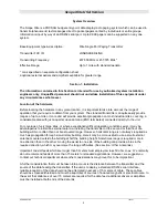
SERIAL PORT (25 way D Type Plug) 


9PIN 

 TO 

         25PIN 

SIGNAL 


DIRECTION 


03


02 

TRANSMIT DATA   

(TX) OUT 

  02 


03 

RECEIVE DATA 


(RX) IN 

  08 


04 

REQUEST TO SEND 

(RTS) OUT 

  07 


05 

CLEAR TO SEND   

(CTS) IN 


05 

  07 

GROUND 

  (GND) 


--- 

  19 

+5V 

   (for 

Scope 

peripherals) 

  04 


20 

DATA TERMINAL READY (DTR) OUT 


As information passes only from the host equipment to the Xlite transcoder, you will only need to read the 
DTR line which, if high at the port pin, shows that power is applied to the Xlite unit. The RTS line will be 
high when the transcoder ‘s ready to receive data. The Xlite RTS line should be connected to the host 
CTS line to facilitate correct handshaking.


Prior to connecting the data cable, thoroughly check the 

system pin connections as shown above.  


Replace the cover and re-fit the two retaining screws. 


7


Power can be provided by way of an AC adapter (part no PTPS12110V, not supplied), or from the 
host system (if suitably equipped) with a12-13.8 volts dc supply, @ 300 mA max. With power 
applied, the red LED on the front cover of the unit should be lit. 

 
8  

The system is now ready to accept calls from the host terminal. When a call is transmitted, the 
green LED on the front cover of the unit will light momentarily. 


Содержание X Lite MK1 XLUK

Страница 1: ...Paging System Model XLUK Scope Marketing Communications UK Ltd The Scope Complex Wills Rd Totnes Devon TQ9 5XN Tel 441803864569Fax 441803863716 XLITE 1 Installation User Manual X Lite MK1 X Lite MK1 X XLite Lite ...

Страница 2: ...nse You should obtain the FCC Rules and Regulations Title 47 Part 80 to End including Parts 90 and 95 available from the US Gov Printing Office GPO Bookstore FCC Office or www fcc gov oet info rules Important Safety Information Scope products are designed to operate safely when installed and used according to general safety practices The following requirements should be observed at all times Do NO...

Страница 3: ...will vary between applications If portable equipment has been dropped or is worn by a person involved in an accident the unit should be tested again before re use It must be stressed that the physical range tests are essential and that any construction work or movement of plant or equipment could alter the signaling capability of the unit Radio equipment like any other requires servicing from time...

Страница 4: ...direct special incidental or consequential damages resulting from any defect in the product even if advised of the possibility of such damages The warranties and remedies set forth above are exclusive and in lieu of all others oral or written expressed or implied No Scope distributor dealer agent or employee is authorized to make any modification extension or addition to this warranty Some states ...

Страница 5: ...nit For coverage of very large sites or where exceptionally difficult operating conditions exist it may be advantageous to install an external antenna Installing the transmitter on the second or third floor of a building will more often than not boost overall range However horizontal range is not always required as much as propagation through a multi story building Here it may be more useful to us...

Страница 6: ... be affected by the type of material the unit is mounted on and its surroundings The following is a list of materials that this transmitter will be adversely affected by if mounted on or if mounted in close proximity to a Foil back wallboard b Metal mesh or wire reinforced glass c Metal sheeting large mirrors or suspended ceilings d Lift shafts All of the above can reflect radio waves and thereby ...

Страница 7: ... antenna which is separate from the transmitter unit itself ensure that the previous criteria covered under the section headed Location of the Hardware have been strictly adhered to also see section headed Other Antennas SERIAL PORT 25 way D Type Plug 9PIN TO 25PIN SIGNAL DIRECTION 03 02 TRANSMIT DATA TX OUT 02 03 RECEIVE DATA RX IN 08 04 REQUEST TO SEND RTS OUT 07 05 CLEAR TO SEND CTS IN 05 07 GR...

Страница 8: ...Scope Xlite USA Version XliteUSA 01 00 Issue 1 7 X L ite ...

Страница 9: ... Check that the communications configuration and protocol on the host matches the system e g 8 N 1 Scope Note auto baud rate detection is from 600 to 9600 baud 3 Check that the pagers are at least 3 meters from the transmitter and aerial Under certain conditions it is possible to flood the pager receivers and corrupt the data received 4 Check that the pagers have the battery installed with the cor...

Страница 10: ...or further details Pre terminated coaxial feeder cables are available for 5 10 or 15 meter requirements Note High frequencies can equate to high power losses Always use quality cable RG58 is only acceptable on cable runs of up to 5 meters We recommend RG213 or equivalent on greater lengths If in doubt consult your dealer subject to license conditions Specifically mounting height and Effective Radi...

Страница 11: ...tter Frequency Range 450 470 MHz Channel Spacing 25 KHz TX Baud Rate 1200 FCC ID No JRNUSASERILINK Serial Port Baud Rate Auto detect from 600 to 9600 Port configuration 8 N 1 default Protocol Scope default General Footprint mm 185 H x 140 W x 42 D dependent on system configuration excluding aerial Scope s policy is one of continuous development and specifications are subject to change without noti...

Страница 12: ...ers are always spaced 8 digits apart This is a function of the POCSAG standard it allows for eight frames in which the pager identity can reside Scope uses frame 0 as a default for most systems as this provides for the fastest pager response when called To avoid system identity clashes transcoders are provided with a base number within the range of 1000 to 1 999 000 If for example a base address o...

Отзывы: