background image

ConneXions CX5   DC, Multi Port Version


CX5DCred 


Issue 2 

Page 

7 of 13 


Section 2: System Operation


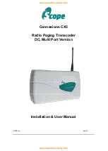
Confirmation of power connection is by way of the red LED on the base of the transcoder 
console. 
 
Confirmation of transmit is provided by way of the momentary green LED on the base of 
the transcoder console. 


Sending data in the correct format (see Technical Section, 

Calling Pagers

) will invoke 

transmitted messages to the relevant pagers. 


Problems and Fault Finding. 
 

Check and re-check the data cable connections. This, together with an incorrect 


signalling format, result in more faults than any other problem. 


Check that the communications baud rate of the host equipment matches that of the 
Connexions COM ports. The default baud rate settings on the Connexions are: 


COM1 = 1200 baud, COM2 = 9600 baud (check configuration data supplied with 
your order, see label on inside of chassis). 


Check that the pagers are at least 3 metres from the transmitter and aerial. 


Under certain conditions it is possible to flood the pager receivers and corrupt the 


data received. 

 
4    

Check that the pagers have the battery installed with the correct polarity and are 
correctly powered up. Check the pager baud rate and frequency matches the 
Connexions transmitter (see label on inside of chassis plate). 


Check that the red power LED on the base of the transcoder is lit. If not, remove the 
power cord and check that 12V DC is available from the source supply.  

 
6  

Check that the green LED lights for the duration of the transmission. If not, go back 


to the data cabling and re-check the signal format. 

 
7  

Check that the aerial is correctly installed.


IMPORTANT: Internal access and adjustments strictly limited to authorised service personnel 
only. 


Radio Transmission Baud Rate 

 
This is set at the factory to suit the pagers supplied and will normally be set at either 512 or 
1200 baud. Please refer to the separate configuration sheet and/or delivery note supplied 
with your unit.


www.acornfiresecurity.com

www.acornfiresecurity.com

Содержание Connexions CX5

Страница 1: ...CX5DCred Issue 2 Connexions CX5 Radio Paging Transcoder DC Multi Port Version Installation User Manual www acornfiresecurity com www acornfiresecurity com ...

Страница 2: ...ts and invoices Alternatively these can be provided on request Faxed proforma invoices and quotations refer to conditions available upon request Important Safety Information Scope products are designed to operate safely when installed and used according to general safety practices The following requirements should be observed at all times Do NOT subject this equipment to Mechanical shock Excessive...

Страница 3: ...function of this product Scope will with proof of purchase repair or replace at it s discretion any defective parts free of charge This does not include where the adjustments parts and repair are necessary due to circumstances beyond the control of Scope including but not limited to fire or other casualty accident neglect abuse abnormal use or battery leakage damage WARNING No User Serviceable Par...

Страница 4: ...of more than 15 metres for standard applications However we suggest you contact our technical dept where other considerations may prove this to be impractical A further consideration is the distance between the transmitter and the source of the data If the unit is to deploy a standard RS232 serial interface reliable reception of the data should not be attempted in excess of 15 metres of cable Thes...

Страница 5: ... Metal mesh or wire reinforced glass c Metal sheeting large mirrors or suspended ceilings d Lift shafts All of the above can reflect radio waves and thereby reduce the capability of the transmitter to perform its desired functions 6 The circuit boards within this equipment may be harmed by Electrostatic Discharge ESD Installers should ensure that both themselves and the system s chassis are ground...

Страница 6: ...lug PIN SIGNAL DIRECTION 1 N C 2 RECEIVE DATA RX IN 3 TRANSMIT DATA TX OUT 4 DATA TERMINAL READY DTR OUT 5 GROUND GND 6 N C 7 REQUEST TO SEND RTS OUT 8 CLEAR TO SEND CTS IN 9 5V 100mA max for Scope peripherals As information passes only from the host equipment to the ConneXions transcoder you will only need to read the DTR line which if high shows that power is applied to the Connexions unit The R...

Страница 7: ...ConneXions CX5 DC Multi Port Version CX5DCred Issue 2 Page 6 of 13 DIAGRAM 1 www acornfiresecurity com www acornfiresecurity com ...

Страница 8: ...s are at least 3 metres from the transmitter and aerial Under certain conditions it is possible to flood the pager receivers and corrupt the data received 4 Check that the pagers have the battery installed with the correct polarity and are correctly powered up Check the pager baud rate and frequency matches the Connexions transmitter see label on inside of chassis plate 5 Check that the red power ...

Страница 9: ...use irreparable damage This unit can support up to 8 dry volt free contacts on PL1 which when shorted to ground will send a pre programmed message to a particular pager address which could be to an individual a group or all pager operatives at the same time These messages are pre programmed and can only be changed by qualified service personnel The trigger time required to send a message must be g...

Страница 10: ...For customers who wish to connect directly to PL1 the pinout arrangement on the 9 way D plug is shown below PL1 9 way D Plug Dry Contact No 1 1 2 3 3 5 4 7 6 2 7 4 8 6 9 8 5 GROUND Test Calls a test call message can be sent every 10 seconds This feature is very useful for site surveys and range testing The default is dry contact no 1 www acornfiresecurity com www acornfiresecurity com ...

Страница 11: ...irst telephone our service hotline where we may request that you undertake a few simple checks If a problem still remains we will arrange collection of your system by overnight carrier at our expense Upon receipt we will endeavour to service or replace the system within 24 working hours and return the same by overnight carrier We suggest that you retain the packaging for your control equipment Inc...

Страница 12: ...ate 512 or 1200 RF Standards applied EN 300 224 V2 1 1 2017 06 EMC Standard applied EN 301 489 2 V2 1 0 2017 03 Safety Standard applied EN 60950 1 2006 A2 2013 General Ports RS232 serial on COM1 COM2 and COM3 USB 8 way dry contact I F Comms Baud Rate 600 to 9600 software adjustable Footprint mm 330 L x 190 W x 70 D max dependent on system configuration excluding aerial subject to applicable countr...

Страница 13: ...ample a base address of 0100 000 is applied to a transcoder the first real pager number will 0100 008 followed by 0100 016 and so on Logical pager numbers are normally used on systems fitted with the telephone interface and those which are interfaced to personal computers The algorithm would perform the following function For example take the logical pager number of 123 The logical pager number 12...

Страница 14: ...be accompanied by the green LED lighting for the same period to show that data is being transmitted The time taken to transmit the message is dependent upon the pager baud rate For 512 baud this is approximately 4 seconds whilst at 1200 baud the time is approximately 2 seconds The unit can accept sequential data at 9600 baud which will be buffered and dealt with as soon as the preceding transmissi...

Отзывы: