


www.science-image.com
1/9
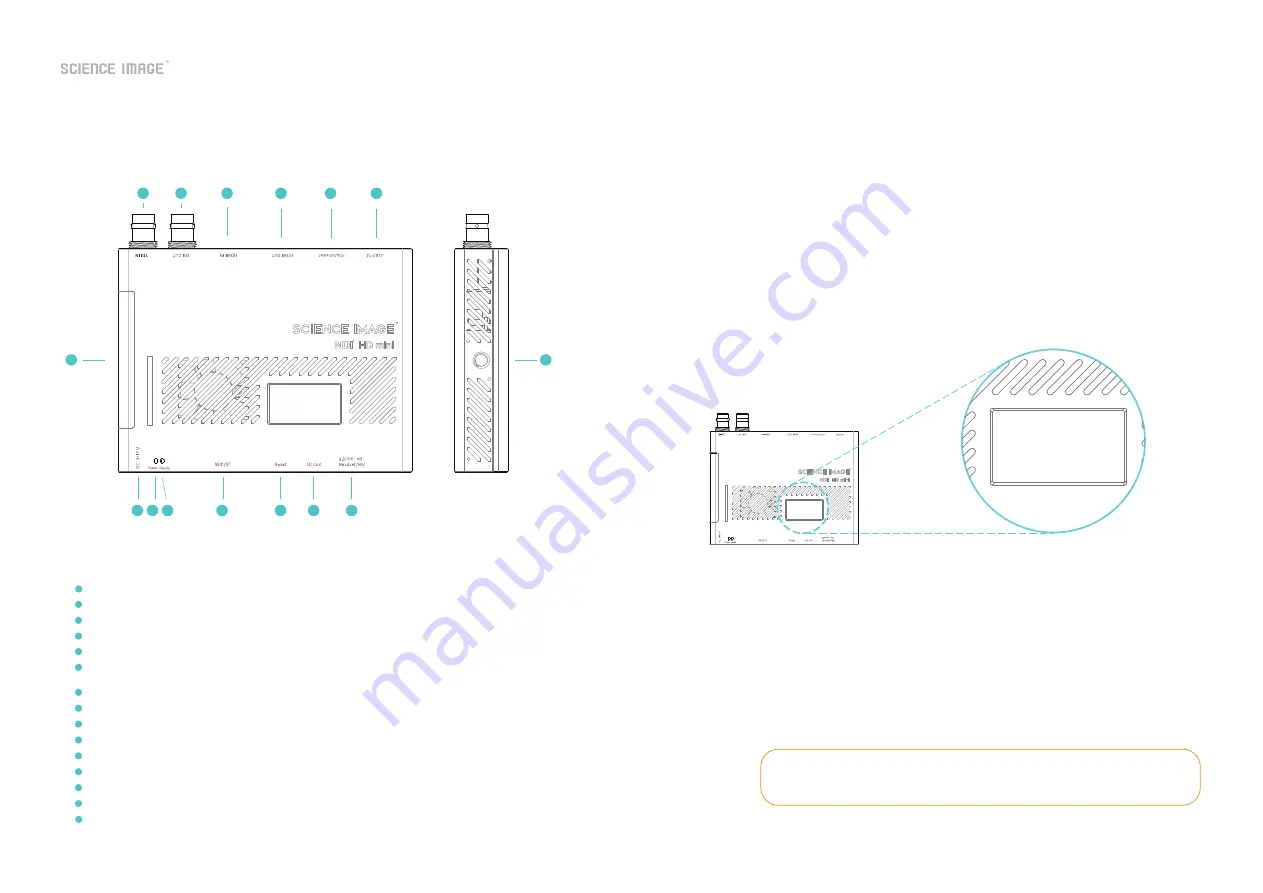
1. NDI® HD mini interface and indicator introduction
2. 3 power-on methods of NDI HD mini
1
2
3
4
5
6
7
8 9 10
12
13
14
11
15
SDI input---------------- 3G-SDI input, only available in encoding state
SDI output---------------3G-SDI output, the picture is looped out in the encoding state, and the decoded output picture in the decoding state
HDMI input---------------HDMI input, only available in encoding state
HDMI output--------------HDMI output, loop out the picture in the encoding state, and decode the output picture in the decoding state
Network port/POE---------network connection/through POE (Power Over Ethernet) switch can be connected to the LAN and powered on at the same time
USB/PTZ-----------------USB mode power supply / support for pan/tilt omni-directional (up and down, left and right) movement and lens zoom,
zoom control camera connection
Tally indicator------------real-time display of the three states of the current broadcast video: yellow/standby, green/pre-monitoring, red/program
Hot shoe hole-------------fixed connection slot with imaging equipment
5-17V DC-IN--------------5-17V DC power input
DC power indicator--------DC power indicator, white light after successful power-on
Start indicator------------the system core chip starts the work indicator, and the green light is displayed when the startup is successful
Wifi and Bluetooth---------Wfi and Blutooth Atena
Reset--------------------manual reset button
SD Card------------------An external boot disk before firmware version 0620a, which is no longer used since 0620a, and the system is moved to flash
Headset or Mic------------headphone jack, adopts American standard; at the same time can be used as Mic
1
2
3
4
5
6
7
8
9
10
12
13
14
15
11
3. OLED screen display instructions
① Use the standard DC-12V power supply of the product to power on, and insert the network cable to connect to the LAN;
② Power on using USB, and insert the network cable to connect to the LAN;
③ Connect to the LAN at the same time through the power of the network cable connected to the POE (Power Over Ethernet)
switch.
After power on, the NDI® HD mini will display four lines of information on the front OLED screen. The specific informationis listed
as follows:
NDI Decoder
NDI: SCIENCEIMAGE
VI: 1920 1080 p50
192.168.1.24
If the NDI® HD mini has been set to the decoding mode, the screen will first display the
default initialization encoding state each time it is first powered on, and it will resume
displaying the currently set decoding state after waiting for about 30 seconds.
NDI Decoder
NDI: SCIENCEIMAGE
VI: 1920 1080 p60
192.168.1.24
The first line:
The second line:
The third line:
The fourth line:
Note:
Displays the current mode of the NDI® HD mini, there are two types: encoding and decoding. The encoding is:
"NDI Encoder"; the decoding is: "NDI Decoder".
Displays the name of the NDI stream currently being encoded or decoded by NDI® HD mini. Such as:
"NDI:SCIM-2020" (encoding end) or "NDI:SCIENCEIMAGE" (decoding end).
Cyclically display the resolution of the video stream currently being encoded or decoded and the type of the
connected video source interface. In the encoding state, first display the resolution of the input video stream,
for example: "VI: 1920x1080P60"; then switch to the connected video source interface type such as
"CH: SDI-1 HDMI-0" (0 means no input, 1 It has input); the video sourceinterface type connected in the decoding
state is displayed as: "CH:NDI-1", which means it is in the state of decoding NDI video stream. When there is no
input at the encoding end, it will display "VI:0x0/0" first and then "CH:SDI-0 HDMI-0".
Cyclically display the current device's IP address, the real-time temperature of the main chip, and the frequency
of the audio codec. For example: "192.168.1.24" and "CPU:56 AI:48khz" are displayed cyclically.


