


4.90
SEL-787 Relay
Instruction Manual
Date Code 20081022
Protection and Logic Functions
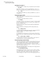
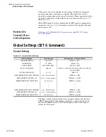
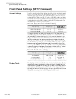
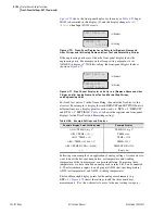
Global Settings (SET G Command)
=>>
SET G AO301AQ TERSE <Enter>
Global
AO 301 Settings
AO301 ANALOG QTY (OFF, 1 analog quantity)
AO301AQ := OFF
? AI301 <Enter>
AO301 TYPE (I,V) AO301TYP:= I ?
<Enter>
AO301 AQTY LO (-2147483647.000 to 2147483647.000)
AO301AQL:= 4.000 ?
4 <Enter>
AO301 AQTY HI (-2147483647.000 to 2147483647.000)
AO301AQH:= 20.000 ?
20 <Enter>
AO301 LO OUT VAL (-20.480 to 20.480 mA) AO301L := 4.000 ?
<Enter>
AO301 HI OUT VAL (-20.480 to 20.480 mA) AO301H := 20.000 ?
<Enter>
AO 302 Settings
AO302 ANALOG QTY (OFF, 1 analog quantity)
AO302AQ := OFF
?
END <Enter>
Save changes (Y,N)?
Y <Enter>
Settings Saved
=>>
Figure 4.58
Analog Output Settings
Digital Input
Debounce
To comply with different control voltages, the SEL-787 offers dc debounce as
well as ac debounce modes. Therefore, if the control voltage is dc, select the
dc mode of operation, and if the control voltage is ac, select the ac mode of
operation. In general, debounce refers to a qualifying time delay before
processing the change of state of a digital input. Normally, this delay applies
to both the processing of the debounced input when used in device logic, as
well as to the time stamping in the SER. Following is a description of the two
modes.
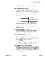
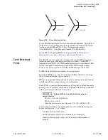
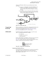
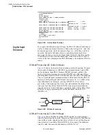
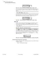
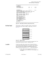
DC Mode Processing (DC Control Voltage)
shows the logic for the dc debounce mode of operation. To select
the dc mode of debounce, set IN101D to any number between 0 and 65000
ms. In the figure, Input IN101 becomes IN101R (internal variable), after
analog-to-digital conversion. On assertion, IN101R starts Debounce Timer,
producing Relay Word bit IN101 after the debounce time delay. The debounce
timer is a pickup/dropout combination timer, with debounce setting IN101D
applying to both pickup (pu) and dropout (do) timers, i.e., you cannot set any
timer individually. For example, a setting of IN101D = 20 ms delays
processing of the input signal by 20 ms (pu) and maintains the output of the
timer (do) for 20 ms. Relay Word bit IN101 is the output of the debounce
timer. If you do not want to debounce a particular input, still use Relay Word
bit IN101 in logic programming, but set the debounce time delay to 0
(IN101D = 0).
Figure 4.59
DC Mode Processing
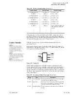
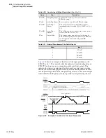
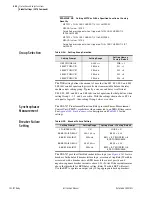
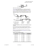
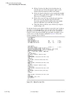
AC Mode Processing (AC Control Voltage)
shows IN101R from Input IN101 applied to a pickup/dropout
timer. Different from the dc mode, there are no time settings for the debounce
timer in the ac mode: the pickup time delay is fixed at 2 ms, and the dropout
time is fixed at 16 ms. Relay Word bit IN101 is the output of the debounce
timer. To select the ac mode of debounce, set IN101D = AC.
pu
do
IN101
Relay
Word
Bit
Input IN101
IN101R
Analog/Digital
Converter
Debounce Timer
Содержание SEL-787
Страница 1: ...20081022 SEL 787 Transformer Protection Relay Instruction Manual PM787 01 NB ...
Страница 6: ...This page intentionally left blank ...
Страница 12: ...This page intentionally left blank ...
Страница 18: ...This page intentionally left blank ...
Страница 78: ...This page intentionally left blank ...
Страница 206: ...This page intentionally left blank ...
Страница 280: ...This page intentionally left blank ...
Страница 334: ...This page intentionally left blank ...
Страница 376: ...This page intentionally left blank ...
Страница 388: ...This page intentionally left blank ...
Страница 474: ...This page intentionally left blank ...
Страница 508: ...This page intentionally left blank ...
Страница 522: ...This page intentionally left blank ...