


Date Code 20010625
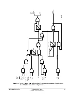
Trip and Target Logic
5-17
SEL-311L Instruction Manual
P
ERMISSIVE
O
VERREACHING
T
RANSFER
T
RIP
(POTT) L
OGIC
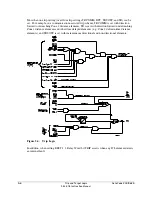
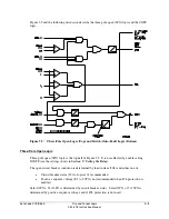
Enable the POTT logic by setting ECOMM = POTT. The POTT logic in Figure 5.8 is also
enabled for directional comparison unblocking schemes (ECOMM = DCUB1 or
ECOMM = DCUB2). The POTT logic performs the following tasks:
v
Keys communication equipment to send permissive trip when any element included in
the SEL
OGIC
control equation communications-assisted trip equation TRCOMM asserts
and the current reversal logic is not asserted.
v
Prevents keying and tripping by the POTT logic following a current reversal.
v
Echoes the received permissive signal to the remote terminal.
v
Prevents channel lockup during echo and test.
v
Provides a secure means of tripping for weak- and/or zero-infeed line terminals.
Use Existing SEL-321 Relay POTT Application Guide for the SEL-311L Relay
Use the existing SEL-321 Relay POTT application guide (AG95-29) to help set up the SEL-311L
Relay in a POTT scheme (see preceding subsection
Communications-Assisted Trip Logic
—
General Overview
for more setting comparison information on the SEL-321/SEL-311L Relays).
External Inputs
See
Optoisolated Inputs
in
Section 7: Inputs, Outputs, Timers, and Other Control Logic
for
more information on optoisolated inputs.
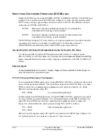
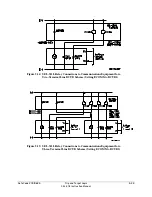
PT1—Received Permissive Trip Signal(s)
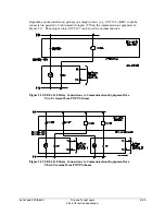
In two-terminal line POTT applications, a permissive trip signal is received from one remote
terminal. One optoisolated input on the SEL-311L Relay (e.g., input IN104) is driven by a
communications equipment receiver output (see Figure 5.10). Make SEL
OGIC
control equation
setting PT1:
PT1 = IN104
(two-terminal line application)
In three-terminal line POTT applications, permissive trip signals are received from two remote
terminals. Two optoisolated inputs on the SEL-311L Relay (e.g., input IN104 and IN106) are
driven by communications equipment receiver outputs (see Figure 5.11). Make SEL
OGIC
control
equation setting PT1 as follows:
PT1 = IN104 * IN106
(three-terminal line application)
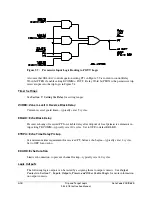
SEL
OGIC
control equation setting PT1 in Figure 5.7 is routed to control Relay Word bit PT if
enable setting ECOMM = POTT. Relay Word bit PT is then an input into the POTT logic in
Figure 5.8 (for echo keying).
Содержание SEL-311L
Страница 6: ......
Страница 8: ......
Страница 26: ......
Страница 54: ......
Страница 144: ......
Страница 203: ...Date Code 20010625 Trip and Target Logic 5 27 SEL 311L Instruction Manual Figure 5 12 DCUB Logic ...
Страница 216: ......
Страница 252: ......
Страница 302: ......
Страница 338: ......
Страница 480: ......
Страница 484: ......
Страница 486: ......
Страница 502: ......
Страница 532: ...12 28 Standard Event Reports and SER Date Code 20010625 SEL 311L Instruction Manual 4 ...
Страница 552: ......
Страница 554: ......
Страница 574: ......
Страница 576: ......
Страница 596: ......
Страница 602: ......
Страница 628: ......
Страница 656: ......
Страница 662: ......
Страница 664: ......
Страница 688: ......
Страница 700: ......
Страница 716: ......
Страница 722: ......
Страница 734: ......