


5-2
Trip and Target Logic
Date Code 20011205
SEL-311B Instruction Manual
From Figure 5.3
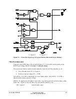
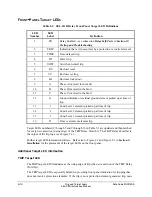
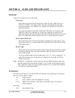
Figure 5.1: Trip Logic
Set Trip
Refer to Figure 5.1. All trip conditions:
·
Direct Transfer Trip
·
Switch-Onto-Fault Trip
·
Other Trips
are combined into OR-1 gate. The output of OR-1 gate asserts Relay Word bit TRIP to logical 1,
regardless of other trip logic conditions. It also is routed into the Minimum Trip Duration Timer
(setting TDURD).
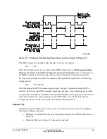
As shown in the time line example in Figure 5.2, the Minimum Trip Duration Timer (with setting
TDURD) outputs a logical 1 for a time duration of “TDURD” cycles any time it sees a rising
edge on its input (logical 0 to logical 1 transition), if it is not already timing (timer is reset). The
TDURD timer ensures that the TRIP Relay Word bit remains asserted at logical 1 for a minimum
of “TDURD” cycles. If the output of OR-1 gate is logical 1 beyond the TDURD time, Relay
Word bit TRIP remains asserted at logical 1 for as long as the output of OR-1 gate remains at
logical 1, regardless of other trip logic conditions.
The Minimum Trip Duration Timer can be set no less than 4 cycles.
Содержание SEL-311B
Страница 6: ......
Страница 8: ......
Страница 10: ......
Страница 24: ......
Страница 26: ......
Страница 122: ......
Страница 124: ......
Страница 138: ......
Страница 168: ......
Страница 172: ......
Страница 254: ......
Страница 282: ......
Страница 306: ......
Страница 348: ......
Страница 364: ......
Страница 366: ......
Страница 448: ......
Страница 460: ......
Страница 466: ......
Страница 476: ......
Страница 482: ......
Страница 494: ......
Страница 500: ......
Страница 522: ......
Страница 526: ......
Страница 528: ......
Страница 534: ......
Страница 536: ......
Страница 550: ......
Страница 570: ......
Страница 586: ......
Страница 600: ......


