Assembly
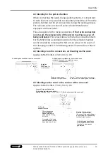
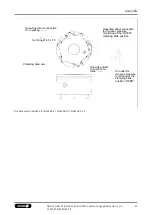
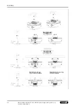
Direct connection from the
installation space with a seal
to the cone seal via the O-ring
Ø 6 x 5.5 (scope of delivery KVS 40)
Air flow for the blow-out
function (2 bar)
Air outlets with closed
quick-change pallet module
4.4 Clamping pins SPA 40, SPB 40, SPC 40, SPG 40
CAUTION
Notes on clamping pins and mounting screws
The holding force of the quick-change pallet system is limited
essentially by the tightness of the screw connection which
connects the clamping pin to the pallet or the device. This is why
only screws of strength class 12.9 may be used.
Only original SCHUNK clamping pins may be used.
If the clamping pins are to be used in customer-owned devices,
the customer must provide sufficiently dimensioned threaded
holes or a sufficiently thick mounting material.
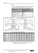
The clamping pins can be attached to the workpiece or pallet in
two different ways. Preference should be given to the left
mounting option in the illustration "Mounting the clamping pins".
With this variant, if there is a module failure then the device or
pallet can be removed after disassembling the clamping pins. The
mounting screw is supplied for the right mounting option as shown
in the illustration.
If clamping pins are used outside of SCHUNK pallets, for example
in customer-specific devices or workpieces, the outer diameter of
the part to be clamped must be large enough to completely cover
the inner support area of the quick-change pallet system and the
outer support areas of the system must be at least partially
covered.
37
08.00 | NSE3 138, NSE-T3 138 | VERO-S quick-change pallet system | en |
1152197 -NSE3 NSE-T3

