


Function
36
02.00|ROTA NCK plus |en
Function
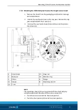
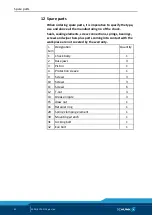
The item numbers specified for the corresponding individual com-
ponents relate to chapter drawings.
Function and handling
Wedge-hook chucks are actuated using rotating closed-center or
open-center hydraulic cylinders or via a static hydraulic cylinder.
The axial tensile and pressure forces are converted to the radial
jaw clamping force by the wedge hook angle in the piston and
base jaws.
The clamping and opening path of the chuck jaws is determined by
the hydraulic cylinder. The fine serration of the base jaws can be
used to mount standard jaws as well as special jaws for complicat-
ed workpiece shapes. The top jaws are moved or changed in the
open clamping position.
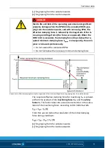
WARNING
Clamping further above the chuck surface results in lower
clamping force.
If the workpiece is released in an uncontrolled manner, there is a
risk of personal injury and damage to the system.
• Refer to the "Technical data" chapter!
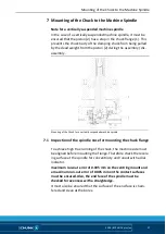
Replacement or renewal of jaws
Clamping jaws for maximum clamping repeat accuracy have to be
bored out or ground out in the clamping chuck under clamping
pressure.
NOTE
During boring or grinding out, be sure that the turning ring or the
turning pins from the top jaws are clamped and not those from the
base jaws.
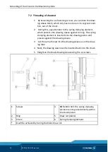
Tighten the jaw mounting screws (screw grade 12.9) with the spec-
ified torque
NOTE
• Tighten the jaw fastening screws with a dynamometric key.
Never carry out this work by using an extension rod or by ap-
plying hammer blows.
8
8.1
8.2


