5
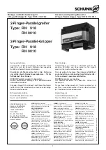
Montage- und Betriebsanleitung für
2-Finger-Parallelgreifer Type RH 918 / RH 9010
Assembly and Operating Manual for
2-Finger-Parallel-Gripper Type RH 918 / RH 9010
3.
Lieferumfang
–
RH 918 / RH 9010
(ohne Aufsatzbacken und Näherungsschalter)
–
1 Schaltfahne mit Befestigungsschraube
ZUBEHÖR:
(bei separater Bestellung, siehe Katalog)
–
Aufsatzbacken
–
induktive Näherungsschalter
4.
Technische Daten
siehe Katalog
–
der von der Einheit ausgehende Luftschall ist
≤
70 dB (A)
5.
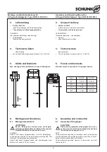
Kräfte und Momente
Max. zulässige Kräfte und Momente an den Greiferfingern
3.
Scope of delivery
–
RH 918 / RH 9010
(without top jaws und proximity switches)
–
1 Control cam with fastening screw
ACCESSORIES:
(if ordered separately – see catalogue)
–
Top jaws
–
Inductive proximity switches
4.
Technical data
(see catalogue)
–
The unit produces air-borne noise at
≤
70 dB (A)
5.
Forces and moments
Max. adm. forces and moments at the gripper fingers
6.
Montage und Anschluss
6.1
Montage des Greifers
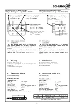
ACHTUNG!
Bei der Montage des Greifers muss die Energie-
versorgung abgeschaltet sein. Beachten Sie auch die
Sicherheitshinweise auf den Seiten 3 und 4.
HINWEIS:
Soweit nicht anders vorgeschrieben, sind alle Befestigungs-
schrauben des Greifers mit einem Anzugsmoment gemäß DIN
oder nach Herstellerangaben anzuziehen.
Soweit nicht anders vorgeschrieben, sind alle Schrauben und
Muttern mit Loctite Nr. 243 zu sichern.
6.
Assembly and connection
6.1
Assembly of the gripper
CAUTION!
Before starting assembly of the gripper, the air con-
nection must be switched off. Please also consider
the safety hints on pages 3 and 4.
NOTE:
Unless otherwise specified, all fastening screws of the gripper
must be tightened with a tightening torque as per DIN or in accor-
dance with the manufacturer's instructions.
Unless otherwise specified, secure all screws and nuts with
Loctite No. 243.
Type
RH 918
RH 9010
F
Z
1150 N
600 N
M
X
7 Nm
14 Nm
M
Y
12 Nm
27 Nm
M
Z
7 Nm
22 Nm
M
X
M
Y
M
Z
F
Z

