background image

Technical data

16

08.00 | PZB-plus | Assembly and Operating Manual | en | 389366

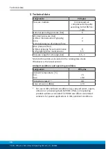
3 Technical data

Designation

PZB-plus

Pressure medium

Compressed air,

compressed air quality

according to ISO 8573-1:

7:4:4

Nominal operating pressure [bar]

6

Minimum pressure [bar] 
without maintenance of gripping
force 
with maintenance of gripping force

2
4

Max. pressure [bar]
without gripping force maintenance
with gripping force maintenance

8

6.5

Pressure range for air purge [bar]

0.5 - 1

More technical data is included in the catalog data sheet.
Whichever is the latest version.

Ambient conditions and operating conditions

Designation

PZB-plus

Ambient temperature [°C]
min.
max.

+5

+90

Protection class IP *

40

Noise emission [dB(A)]

≤ 70

* For use in dirty ambient conditions (e.g. sprayed water, vapors,

abrasion or processing dust) SCHUNK offers corresponding
product options as standard. SCHUNK also offers customized
solutions for special applications in dirty ambient conditions.

Содержание PZB-plus 100

Страница 1: ...Translation of the original manual Assembly and Operating Manual PZB plus 3 Finger Centric Gripper...

Страница 2: ...erations for the purpose of technical improvement Document number 389366 Version 08 00 30 08 2019 en SCHUNK GmbH Co KG All rights reserved Dear Customer thank you for trusting our products and our fam...

Страница 3: ...r fingers 9 2 6 Environmental and operating conditions 9 2 7 Personnel qualification 10 2 8 Personal protective equipment 10 2 9 Notes on safe operation 11 2 10 Transport 11 2 11 Malfunctions 11 2 12...

Страница 4: ...position sensor APS Z80 37 5 3 14 Mounting the radio system RSS R1 T2 39 5 3 15 Mounting FMS force measuring jaw 39 6 Troubleshooting 40 6 1 Product does not move 40 6 2 Product is not executing the...

Страница 5: ...is manual Illustrations in this manual are provided for basic understanding and may differ from the actual product design In addition to these instructions the documents listed under Applicable docume...

Страница 6: ...us 100 PZB plus 125 PZB plus 160 PZB plus 200 PZB plus 240 PZB plus 300 1 1 4 Variants This operating manual applies to the following variations PZB plus PZB plus with gripping force maintenance O D g...

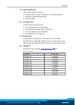
Страница 7: ...rew plug for hose connection 2x Cylinder pins for mounting 1 4 Accessories A wide range of accessories are available for this product For information regarding which accessory articles can be used wit...

Страница 8: ...n in a machine system The applicable guidelines must be observed and complied with The product is intended for industrial and industry oriented use Appropriate use of the product includes compliance w...

Страница 9: ...ant property damage Arrange the gripper fingers in a way that the product reaches either the position open or closed in a de energized state Only exchange the gripper fingers when no residual energy r...

Страница 10: ...ated tasks recognize and avoid possible dangers and knows the relevant standards and regulations Instructed person Instructed persons were instructed by the operator about the delegated tasks and poss...

Страница 11: ...rect handling during transport may impair the product s safety and cause serious injuries and considerable material damage When handling heavy weights use lifting equipment to lift the product and tra...

Страница 12: ...the product s safety and cause serious injuries and considerable material damage Have all work carried out by appropriately qualified personnel For all work secure the product against accidental opera...

Страница 13: ...ue through technical safety measures The protective cover and protective fence must be rigid enough to withstand the maximum possible movement energy EMERGENCY STOP switches must be easily and quickly...

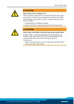
Страница 14: ...ve measures to secure the danger zone WARNING Risk of injury due to unexpected movements If the power supply is switched on or residual energy remains in the system components can move unexpectedly an...

Страница 15: ...unexpectedly and cause serious injuries Disassemble the product cautiously Make sure that no residual energy remains in the system WARNING Risk of injury from objects falling during energy supply fai...

Страница 16: ...e maintenance with gripping force maintenance 8 6 5 Pressure range for air purge bar 0 5 1 More technical data is included in the catalog data sheet Whichever is the latest version Ambient conditions...

Страница 17: ...anual en 389366 17 4 Design and description 4 1 Design 3 Finger Centric Gripper 1 Housing 2 Base jaw 3 Compressed air main connection 4 2 Description Universal 3 finger centric gripper with high gripp...

Страница 18: ...of the fingers is exceeded the gripper can be damaged A jaw movement always has to be without jerks and bounce You must therefore implement sufficient reduction and or damping Observe the diagrams an...

Страница 19: ...anical connection 20 Observe the maximal tightening torque admissible screw in depth and if necessary strength class Secure the gripper fingers to the base jaws Mechanical connection 20 Use centering...

Страница 20: ...pter plates If the adapter plate has bores or recesses and therefore the product is not fully flush the minimum support surface must be adhered to The recess bore in the adapter plate may not exceed t...

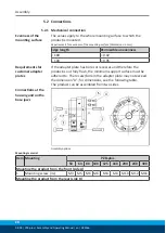
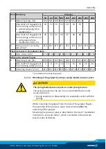
Страница 21: ...x M2 5 M3 M4 M5 M6 M6 M12 M12 M16 Max depth of engagement from locating surface mm 6 8 10 10 13 13 16 20 28 5 Centering sleeve mm 4 5 6 8 10 10 16 16 22 Contained in accessory pack 5 2 1 1 Mounting of...

Страница 22: ...ecure position However the use of a SDV P pressure maintenance valve is recommended in this case in order to maintain the dynamic effect for some time Product variants are also offered with mechanical...

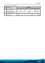
Страница 23: ...9366 23 Thread diameter of the air connections Ite m Connection PZB plus 50 64 80 100 125 160 200 240 300 1 Main connections Hose connection 2x M5 2x G1 8 2x G1 4 2 Air purge connection M5 3 Hose free...

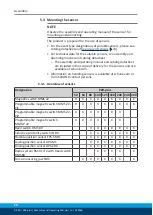
Страница 24: ...the sensors and are available at schunk com Information on handling sensors is available at schunk com or from SCHUNK contact persons 5 3 1 Overview of sensors Designation PZB plus 50 64 80 100 125 1...

Страница 25: ...per jaw X 10 mm 10 of the nominal stroke per jaw Example Product with 7 mm nominal stroke per jaw 7 mm 20 1 4 mm 5 3 3 Turn control cam Turn control cam example control cam for inductive monitoring D...

Страница 26: ...MMS 22 PI2 Programmable magnetic switch MMS P 22 Size l1 mm Size l1 mm PZB plus 50 24 3 PZB plus 125 34 5 PZB plus 50 AS 34 3 PZB plus 125 AS 60 9 PZB plus 50 IS 34 0 PZB plus 125 IS 60 9 PZB plus 64...

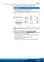
Страница 27: ...end of the groove Pull the sensor 1 1 back again slowly until it switches Secure the sensor 1 1 using the set screw 4 Tightening torque 10 Ncm Bring product into the Gripper open or Part gripped posit...

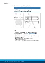
Страница 28: ...2 until the sensor 1 1 stops at the T nut 3 Secure the sensor 1 1 using the set screw 4 Tightening torque 10 Ncm Adjust sensor 1 1 see sensor assembly and operating manual Repeat steps for sensor 2 Si...

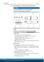
Страница 29: ...maximal tightening torque NOTE If there is no T nut available slide the sensor according to dimension I1 into the groove 2 Setting dimensions 26 Turn the sensor 1 into the groove 2 OR Slide the senso...

Страница 30: ...maximal tightening torque NOTE If there is no T nut available slide the sensor according to dimension I1 into the groove 2 Setting dimensions 26 Turn the sensor 1 into the groove 2 OR Slide the sensor...

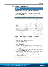
Страница 31: ...r 1 1 or sensor 2 1 to the stop into the bracket 2 Tighten the screw 3 on the bracket 2 Tightening torque 0 2 Nm Open gripper or grip part Undo the screw 4 Turn the screw 5 to push the position of the...

Страница 32: ...rew 5 to push the position of the control cam 6 Slide control cam 6 outwards until the sensor 3 1 no longer responds Move the control cam 6 back towards the inside until the sensor 3 1 begins to switc...

Страница 33: ...sensor 1 1 or sensor 2 1 to the stop into the bracket 2 Tighten the screw 3 on the bracket 2 Tightening torque 0 2 Nm Open gripper or grip part Undo the screw 4 Turn the screw 5 to push the position...

Страница 34: ...rew 5 to push the position of the control cam 6 Slide control cam 6 outwards until the sensor 3 1 no longer responds Move the control cam 6 back towards the inside until the sensor 3 1 begins to switc...

Страница 35: ...a special mounting kit Move product to the gripper open position Loosen screw 4 and remove control cam 6 for the inductive monitoring from the base jaw Remove screw 5 from the base jaw Slide control...

Страница 36: ...he inductive monitoring from the base jaw Apply adhesive to the top and sides of the control cam 6 from the mounting kit Make sure that there is no adhesive on the bottom of the control cam 6 which co...

Страница 37: ...aw Apply the switching cam in the direction of the base jaw so that the cam does not contact the housing of the gripper During the monitoring process the first 8 of the nominal stroke will not produce...

Страница 38: ...which comes into contact with the sensor SCHUNK recommends the adhesive Loctite 290 or 638 Slide control cam 6 into the base jaw to the stop Ensure that the higher front side of the control cam 6 is...

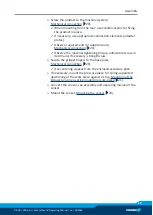
Страница 39: ...nual for the sensor Connect the radio system see the assembly and operating manual for the radio system 5 3 15 Mounting FMS force measuring jaw Screw passive force measuring jaw 1 and active force mea...

Страница 40: ...lace component or send it to SCHUNK for repair 6 2 Product is not executing the complete stroke Possible cause Corrective action Dirt deposits between cover and piston Clean and if necessary re lubric...

Страница 41: ...ngs on the product to the maximum that the movement of the jaws occurs without bouncing and hitting Check compressed air lines Inner diameters of compressed air lines are of sufficient size in relatio...

Страница 42: ...vice Therefore we recommend to have the module serviced and the seals replaced by SCHUNK 7 2 Maintenance intervals CAUTION Material damage due to hardening lubricants Lubricants harden more quickly at...

Страница 43: ...ication nipple 7 4 Disassembly and assembly 7 4 1 Version without gripping force maintenance Position of the item numbers Assembly drawing 47 WARNING Risk of injury when the machine system moves unexp...

Страница 44: ...ws 2 and the cover 9 in the vise such that it is still possible to remove the 4 screws 46 Unscrew the screws 46 Carefully open the bench vise and remove the cover 9 Remove the cylindrical pin 57 WARNI...

Страница 45: ...open the bench vise to remove the surface tension of the pressure spring 26 Remove the cover 9 and remove the compression spring 26 Mark the installation position of the cylinder piston 10 in the hou...

Страница 46: ...PZB plus Assembly and Operating Manual en 389366 8 Assembly drawing The following figure is an example image It serves for illustration and assignment of the spare parts Variations are possible depen...

Страница 47: ...ng with gripping force maintenance I D gripping without gripping force maintenance Assembly of variants Wearing part replace during maintenance Included in the seal kit Seal kit can only be ordered co...

Страница 48: ...Centric Gripper PZB plus pneumatic ID number 0304950 0304975 0305140 0305194 The partly completed machine may not be put into operation until conformity of the machine into which the partly completed...

Страница 49: ...ntial Requirements 1 1 1 Definitions X 1 1 2 Principles of safety integration X 1 1 3 Materials and products X 1 1 4 Lighting X 1 1 5 Design of machinery to facilitate its handling X 1 1 6 Ergonomics...

Страница 50: ...4 2 2 Interlocking movable guards X 1 4 2 3 Adjustable guards restricting access X 1 4 3 Special requirements for protective devices X 1 5 Risks due to other hazards 1 5 1 Electricity supply X 1 5 2 S...

Страница 51: ...quirements for certain categories of machinery X 2 1 Foodstuffs machinery and machinery for cosmetics or pharmaceutical products X 2 2 Portable hand held and or guided machinery X 2 2 1 Portable fixin...

Страница 52: ...52 08 00 PZB plus Assembly and Operating Manual en 389366...

Отзывы: