background image


_________________________________________________________________________________________ 

schunk.com 


XND.00041.002_B – 05/2022   


 33


Raw workpiece clamping (with lift-off)
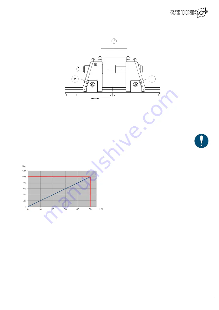
 

5.2

With the raw part clamping it is possible to clamp with simpler set-up and greater clamping forces.  


Position fixed support jaw and tighten the cylinder screw 1 with a torque of 140 Nm.  


Cylinder screw 1 at the movable support jaw remains loose and workpiece is clamped with the 
desired clamping force. 

Important: 

Significantly higher clamping forces are achieved with the raw workpiece clamping. 
Make sure that the torque of 100 Nm is not exceeded to overload the clamping system in 
the long run. 

Raw part clamping KSX-C2 125 and KSX-C2 125-L 


Содержание KSX-C2

Страница 1: ..._______________ schunk com XND 00041 002_B 05 2022 1 Montage und Betriebsanleitung Installation and operating instruction 5 Achs Spanner mit Schnellwechselbacken 5 axis vice with Quick change jaws KSX C2 H D SCHUNK GmbH Co Spanntechnik KG Lothringer Strasse 23 D 88512 Mengen ...

Страница 2: ...tion of the clamping device 29 3 Function 29 3 1 Operation standard operation 30 4 Clamping aligning 30 4 1 Jaw range 31 4 2 Fitting the system jaws 31 4 3 Clamping procedure 32 5 Precision clamping without lifting 32 5 1 Raw workpiece clamping with lift off 33 5 2 Troubleshooting eliminating faults 34 6 General clearing lubrication 34 6 1 Disasembly assembly of the spindle 35 6 2 Cleaning the spi...

Страница 3: ...es a potentially dangerous situation If the information is ignored it is possible that death or serious injury permanent disability will result WARNING Indicates a potentially dangerous situation If the information is ignored it is possible that material damage and light to medium injury will result Information on useful tips or for preventing material damage NOTE Indicates general information use...

Страница 4: ...issioning installation and operating instructions and with the environmental and service conditions as provided by the manufacturer The manufacturer accepts no liability for damage resulting from non intended use Technical data 2 1 1 Version max torque max clamping force KSX C2 125 Raw part clamping 100 Nm 50 kN KSX C2 125 Precision clamping 120 Nm 40 kN KSX C2 125 L Raw part clamping 100 Nm 50 kN...

Страница 5: ...y application that is not in accordance with the Intended use or exceeds such intended use is considered not in accordance with the regulations and is forbidden Any other use of the device is subject to confirmation from the manufacturer Examples of forseeable misapplication Clamping device used on rotating systems Clamping widely protruding workpieces Clamping workpieces with a weight of over 20 ...

Страница 6: ...w change 2 3 1 Damage may result if system jaws are insufficiently fastened Notes on clamping technology 2 3 2 The operator is responsible for ensuring that the clamping geometry and clamping forces are suitable for the intended processing The clamping forces can only be achieved if the clamping device functions correctly and the workpiece is correctly held in the device Regular servicing and clea...

Страница 7: ...quipment 2 7 WARNING Risk of eye injury through ejected hot fragments Ejected hot fragments can lead to serious eye injury The regulations for safety at work and the prevention of accidents always have to be observed when working with the machine Personal protection equipment must be worn at all times in particular safety boots gloves and safety goggles Warranty 2 8 The warranty period is 24 month...

Страница 8: ... to complete encapsulation Raw parts clamping with jaw lift off At 100 Nm torque is the clamping force 50 kN Precision clamping without jaw lifting At 120 Nm torque the clamping force is 34 kN for the S version and 40 kN for the standard version Improper use and clamping with too high torques will cause damage to the spindle and jaws Function 3 1 The clamping range can be quickly adjusted by turni...

Страница 9: ...ymmetrical distance of the two clamping claws is 100 to 150 mm For a base plate length of 630 and 800 mm use at least six clamping claws with a distance of 150 mm for the length 630 mm or 200 mm for the length 800 mm to the center of the vice Alignment with alignment pins 1 precision sliding blocks 2 or fitting screws 4 The base plate is fitted with an interface to attaching the clamping pin for t...

Страница 10: ... clamping device is significantly affected by the selection of the correct system jaws Fitting the system jaws 4 3 Basically no tools are necessary for assembly The system jaws are clicked in from above via a quick change system 1 and can be rotated 180 To remove the system jaws we recommend turning a screwdriver in the opening under the system jaw to the jaw clicks out ...

Страница 11: ...nge is adjustet with the movable support jaw by placing the system jaw 1 2 mm in front of the workpiec Tighten the cylinder screw 1 at the movable support jaw with a torque of 140 Nm Clamp the workpiece on the spindle with the desired clamping force Important The cylinder screw must be tightened to 140 Nm and it must not clamped without the workpiece as otherwise the carrier jaws could shift and c...

Страница 12: ... clamping forces Position fixed support jaw and tighten the cylinder screw 1 with a torque of 140 Nm Cylinder screw 1 at the movable support jaw remains loose and workpiece is clamped with the desired clamping force Important Significantly higher clamping forces are achieved with the raw workpiece clamping Make sure that the torque of 100 Nm is not exceeded to overload the clamping system in the l...

Страница 13: ... moving support jaw at regular intervals or every two weeks When changing pull rod extensions ensure sufficient lubrication If creaking noises occur during operation lubricate the spindle dry running guides immediately General clearing lubrication 6 1 Remove the system jaws 1 Release the lock 2 and remove the spindle 3 Loosen the carrier jaws 5 4 and extend Clean and oil the base plate guide surfa...

Страница 14: ...on 3 Place screwdriver in groove 4 and pull the spindle 2 out of the support jaw The procedure can also performed by released the lock 5 of the spindle 2 and pushing the spindle 2 out first Cleaning the spindle 6 3 Unscrew the spindle completely Clean and lubricate with high pressure grease When assembling make sure that the seal is seated correctly Stroke limitation The spindle is completely enca...

Страница 15: ... right with thread M16 1 120 Bracket left with counterbore M16 1 130 Bracket right with counterbore M16 1 140 Base plate 1 150 Mechanical spindle 1 160 Spindle lock 2 170 Internal hexagon cylinder screw M16x120 12 9 2 180 Spiral spring 1 40x5 70x22 00 2 190 Lens head screw M 2 5x5 2 200 Internal hexagon cylinder screw M6x14 2 210 Internal hexagon threaded pin M6x6 1 220 O ring NBR 70 53 00x5 00 2 ...

Страница 16: ...g Installation Both carrier jaws 1 must be clamped and the rear locks 5 released Turn the spindle 2 until the pull rod extension 3 is pressed out of the support jaw Remove the pull rod extension 3 Release clamping claws 1 Insert the pull rod extension 5 6 or 7 screw on and close the lock 5 Position carrier jaws and tension the clamping claws 1 with 140 Nm ...

Страница 17: ... 3 8 and 18 mm Processing the second side Clamping with the tungsten carbide coated side of the 6 fold reversible jaw It is important to take into account that during the first clamping process the 6 fold reversible jaws can yield slightly until the play in the peg seating is eliminated The workpiece position must be measured the zero point should not be determined until after 3 to 5 power clampin...

Страница 18: ...ersible jaws 9 5 Determine the mounting positions of the 6 fold reversible jaws The best clamping results are achieved when clamping parts as far out as possible Move the cover screws so that the selected clamping position is available Position the 6 fold reversible jaws and loosely insert the cylinder screws Turn the 6 fold reversible jaws on to the required clamping faces and slightly pre clamp ...

Страница 19: ...aws soft 10 Important Max milling depth 15 mm Precision jaws set 11 The precision jaws must be hard milled in the precision clamping with 60 Nm clamping force according to the views For machining in the standard position must the supplied reference tip and for the VS position a gauge block used Important Max milling depth 0 15mm 0 1mm ...

Страница 20: ...er be installed Raw part clamping KSX C2 125 and KSX C2 125 L Precision clamping KSX C2 125 Precision KSX C2 125 L Exposure to loads in excess of the max hydraulic pressure of 250 bar results in damage to the spindle Recommended operating medium hydraulic oil HLP 15 HLP 46 Important The hydraulic supply hose must be vented before connecting it to the vice Once the hose is connected carry out some ...

Страница 21: ... a trapping risk Maintaining pressure during operation It is possible that hydraulic cylinders have small leaks During milling work the clamping device must be continuously supplied with hydraulic pressure from the hydraulic system in order to ensure that there is no loss of pressure due to leakage Hydraulic hoses must be protected against hot fragments hoses must be regularly checked for wear Imp...

Страница 22: ...uirements of the Machinery Directive 2006 42 EC The incomplete machine may not be put into operation until conformity of the machine into which the incomplete machine is to be installed with the provisions of the Machinery Directive 2006 42 EC is confirmed Applied harmonized standards especially EN ISO 12100 2011 03 Safety of machinery General principles for design Risk assessment and risk reducti...

Страница 23: ...____________________________________________________________ schunk com XND 00041 002_B 05 2022 44 H D Schunk GmbH Co Spanntechnik KG Lothringer Strasse 23 D 88512 Mengen Tel 49 7572 7614 0 Fax 49 7572 7614 1099 info de schunk com ...

Отзывы: