Maintenance
03.00 | GSM-W | Assembly and operating manual | en | 389108
47
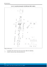
8.10 Disassembly/assembly of the FAN rotor drive (50)
Position of the item numbers
Disassembly
Ø
Remove the compressed air lines.
Ø
Loosen the screws (101) and take the upper housing (51) off the
lower housing (52).
Ø
Remove the O-rings (109) and the centering sleeve (108).
Ø
Take the rotor (53) out of the housing (52) and pull the bearing
(100) off the rotor.
Ø
Pull the O-rings (110) off the rotor.
Ø
Remove the stop rotor (58) and pull the stop seal (59) off the
stop rotor.
Ø
Clean all parts thoroughly and check all parts for defects and
wear.
Ø
Renew the seals listed in the seal set.
Assembly
Ø
Lubricate the upper and lower housing (51 and 52) from the
inside.
Ø
Grease the entire stop rotor (58).
Ø
Pull the stop seal (59) into the correct position on the stop rotor
(58) and grease the two parts completely again.
Ø
Put the stop rotor in the correct position in the intended fit in
the upper rotor housing (51).
Ø
Grease the entire rotor (53) except for the rectangular section.
Ø
Pull both O-rings (110) onto the rotor and lubricate them.
Ø
Stick the ball bearing onto the rotor.
Ø
Stick the rotor with the rectangular part facing down into the
upper housing. Move the rotor into the 90° position, which
means opposite the stop rotor (53).
Ø
Put the centering sleeve (108) in the upper housing (51) for
assembly with the lower housing (52).
Ø
Lubricate four O-rings (109) and place them into the provided
mirrored views in the lower housing (52).
Ø
Mount the upper housing with the lower housing and attach
both with screws (101). The screws (101) are to be tightened
"crosswise".
Ø
Lubricate two O-rings (109) and fit them into the upper housing
(51) into the appropriate counterbores.
Ø
Mount the centering sleeve (108) or cylindrical pin (107) onto
the upper housing (51).


