


SMA Solar Technology AG
Operating Modes
User Manual
SB_SMC_Schueco-BEN093730
11
3 Operating Modes
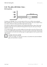
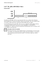
The different operating modes are indicated by 3 light-emitting diodes (LEDs) on the inverter lid, and
also via the integrated display (see Section 4 "Information on the Display" (page 24)). To allow the
device to signal its operating mode via the 3 integrated LEDs, the inverter must be connected to the
DC side of the system. The level of solar irradiation must be high enough to supply the inverter with
sufficient DC voltage.
The following diagram shows the 3 LEDs, as exemplified by the Sunny Boy 3800.
A detailed description of the possible LED signals and blink codes is given in the following section.
LED
Meaning
Inverter
Green
In operation
All Sunny Boys / Sunny Mini Centrals
Red
Ground fault or varistor
defective
For the Sunny Boy models SB 1100, SB 1200,
SB 1700, SB 2100TL, SB 2500, SB 3000, SB 3300,
SB 3300TLHC, SB 3800
and Sunny Mini Central models SMC 4600A,
SMC 5000A, SMC 6000A, SMC 7000HV,
SMC 6000TL, SMC 7000TL, SMC 8000TL.
Ground fault, varistor defective
or string fuse defective
For Sunny Mini Central models SMC 9000TL-10,
10000TL-10, 11000TL-10 and SMC 9000TLRP-10,
10000TLRP-10, 11000TLRP-10
Yellow
Disturbance
All Sunny Boys / Sunny Mini Centrals
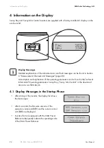
LED Display
If you do not have any means of plant communication, it is advisable, particularly during
the first year of operation, to keep a close eye on this display at different times of day and
under varying solar irradiation conditions. This will enable you to recognize errors at an
early stage.


