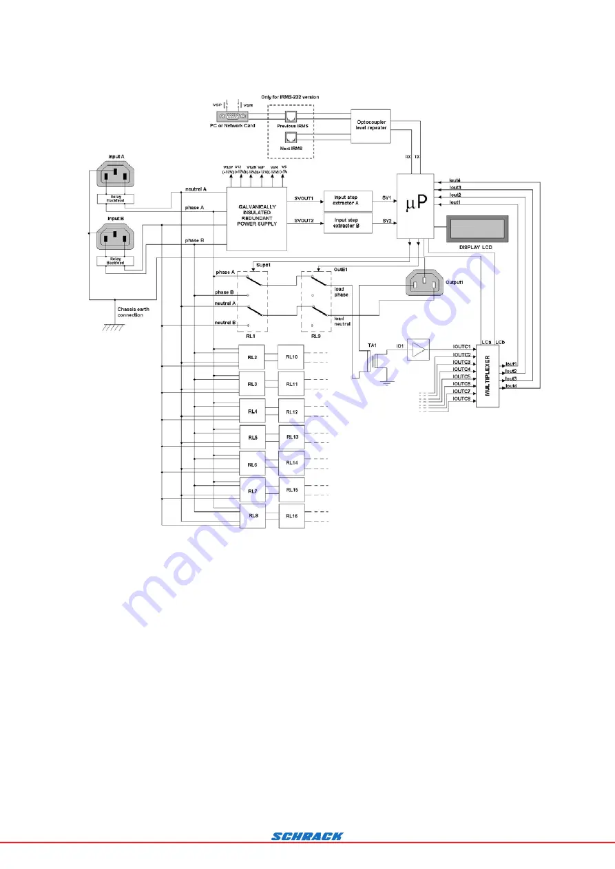
Figure 1:
Block diagram of the IRMS
So that it will operate when at least one of the two lines “A” or “B” is present, the power supply is redundant.
Relays RL1, RL2, RL3, RL4, RL5, RL6, RL7, RL8 switch the output loads from line A to line B, whilst relays RL9, RL10,
RL11, RL12, RL13, RL14, RL15, RL16 disconnect the loads.
4


