schmersal TESK Series Скачать руководство пользователя страница 4

4

Operating instructions

Hinge safety switch

TESK

EN

The minimum bending radius must be observed for versions 

with a cable connection!

Please note the load information "Determining the  

permissible forces as a function of door size and number  

of hinges" (see Section 7.3 Load details)

The hinge safety switch must not be used as an end stop.  

For applications in which heavy doors are used and for use 

on hoods, especially if these can close with little or no braking 

effect, further measures are to be implemented to prevent the 

securing bolts from working loose. A reduction in the service 

life is also expected. The use of hydraulic struts on hoods 

is not permitted as otherwise the hinge switch would be 

 damaged beyond repair.

Fig. 4

Please observe the relevant requirements of the standards 

ISO 12100, ISO 14119 and ISO 14120. Also observe the 

safety distances to the standards ISO 13857 and EN 349.

3.2  Adjustment and inspection of the switching angle

After the switch has been fitted, the switching function and the opening 

angle of the safety guard must be checked. The switching angle of the 

NC contacts set in factory is approximately 3°.

Caution: for the TESK...-U version, the following paragraph 

"Special instructions for the on-site setting" must be observed!

Special instructions for the on-site setting (version TESK...-U)

We recommend a setting including the following steps:

1.  Open guard system up to maximum permissible door gap  

(see table chapter 7.2 Determining door gap).

2.  Use the adjustment tool to set the normally-closed contacts in such 

a way that they are securely opened with the maximum permissible 

door gap. Turning clockwise results in a smaller switch angle while 

turning anticlockwise results in a larger switch angle (fig. 6); this is 

the opposite when mounted inside. To decrease the switching angle, 

turn counterclockwise to increase the switching angle (Fig. 6); when 

mounted inside accordingly reversed.The positive break angle is 7° 

larger than the set switching angle.

3.  After the switch is set, the compliance of the switch with the  

safety-technical requirements of the application must be checked 

(see Section 7.2 Door gap calculation).

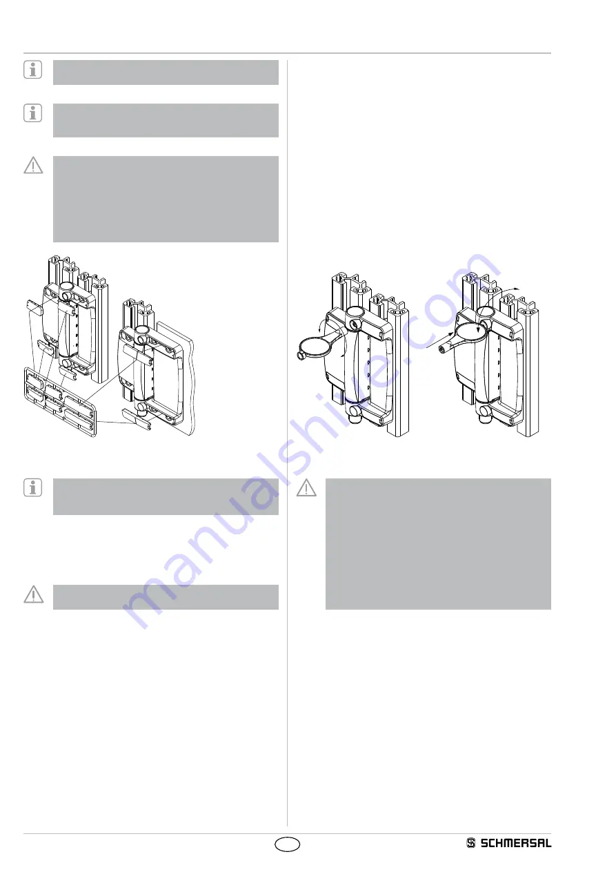
4.  After the switching angle has been set and checked, the blanking 

plug for the adjustment opening located at the rear of the adjustment 

tool must be inserted in the adjustment opening (1) and torn down  

by making lateral movements (2) with the tool (Fig. 7).

-

+

1

2

Fig. 6

Fig. 7

After the desired switching point is set, the opening of the set-

ting option imperatively must be sealed with a blanking plug.

This measure prevents tampering at the set switching point 

within the meaning of ISO 14119 paragraph 5.7 and therefore 

avoids any loss of the safety function of the device.

The blanking plug is injected to the special adjustment tool 

with a predetermined breaking point.

We recommend an additional painting or glueing of the 

blanking plug.

Securing the setting screw by means of the blanking plug is a 

mandatory instruction for the user, which must be oberved in 

order to maintain the CE-Conformity of the component.

Содержание TESK Series

Страница 1: ...ively used in accordance with the versions listed below or for the applications authorised by the manufacturer Detailed information regarding the range of applications can be found in the chapter Product description 1 5 General safety instructions The user must observe the safety instructions in this operating instructions manual the country specific installation standards as well as all prevailin...

Страница 2: ...ne movable safety guards from being opened before hazardous conditions have been eliminated They are also suitable for fitting on profile sections and existing equipment Hinge safety switches can only be used for applications in which the hazardous condition is terminated without delay e g run on movements when the safety guard is opened The user must evaluate and design the safety chain in accord...

Страница 3: ...specific parameters hop dop and tcycle as well as the load If multiple safety components are wired in series the Performance Level to ISO 13849 1 will be reduced due to the restricted error detection under certain circumstances 3 Mounting 3 1 General mounting instructions During fitting of the actuator and the sensor the requirements of ISO 14119 especially paragraph 7 must be observed Four elonga...

Страница 4: ...see table chapter 7 2 Determining door gap 2 Use the adjustment tool to set the normally closed contacts in such a way that they are securely opened with the maximum permissible door gap Turning clockwise results in a smaller switch angle while turning anticlockwise results in a larger switch angle fig 6 this is the opposite when mounted inside To decrease the switching angle turn counterclockwise...

Страница 5: ...urements in mm TESK S TESK ZS 116 101 6 1 66 8 82 20 78 15 15 5 15 40 17 5 TESK L TESK ZL 60 15 15 5 37 5 15 20 6 1 116 66 8 82 20 98 101 TESK ST 11 TESK L Ø 6 6 70 70 B Ø 5 8 C D Key B Minimum bending radius of the connection cable C Cable 5 core B 29 mm D Cable 9 core B 33 mm ...

Страница 6: ...1 4 TESK 11ST 11 23 12 24 PE 1 2 3 4 5 3 2 5 1 4 4 3 Switch travel TESK 22 TESK 13 10 180 3 11 12 31 32 43 44 23 24 A A 10 180 3 11 12 31 32 41 42 23 24 A A A TESK 12 TESK 02 10 180 3 11 12 31 32 23 24 A A 10 180 3 11 12 21 22 A A TESK 11 10 180 3 11 12 23 24 A Key A Positive break NC contact T Positive break travel angle Switching angle tolerance 1 3 5 Set up and maintenance 5 1 Functional testin...

Страница 7: ...M12 8 pole 5 8 4 3 2 1 7 6 Pin configuration of the connector Colour code or conductor numbering of the below mentioned Schmersal connectors Possible colour code of other commercially available connectors to EN 60947 5 2 2007 DIN 47100 Connecting cables with female connector IP67 M12 8 pole 8 x 0 23 mm 1 BN 1 BN WH 2 WH 2 WH BN Cable length Part number 3 BU 3 BU GN 2 5 m 5 0 m 10 0 m 103011411 103...

Страница 8: ... 109 7 127 9 146 1 164 2 182 2 1 100 57 5 76 7 95 8 114 9 134 0 153 0 172 0 190 9 1 150 60 2 80 2 100 2 120 1 140 1 160 0 179 8 199 6 1 200 62 8 83 7 104 5 125 4 146 2 166 9 187 6 208 3 1 250 65 4 87 2 108 9 130 6 152 3 173 9 195 4 217 0 1 300 68 0 90 6 113 2 135 8 158 4 180 8 203 3 225 6 1 350 70 6 94 1 117 6 141 0 164 4 187 8 211 1 234 3 1 400 73 2 97 6 122 0 146 3 170 5 194 7 218 9 243 0 1 450 ...

Страница 9: ...r doors the have three hinges make sure the two of the hinges are located in the upper third We recommend that the safety hinge switch is placed in the middle when three hinges are used The hinge safety switch must not be used as an end stop For applications in which heavy doors are used especially if these can close with little or no braking effect further measures are to be implemented to preven...

Страница 10: ...lation of the technical documentation Oliver Wacker Möddinghofe 30 42279 Wuppertal Place and date of issue Wuppertal April 20 2016 Authorised signature Philip Schmersal Managing Director EU Declaration of conformity Original K A Schmersal GmbH Co KG Möddinghofe 30 42279 Wuppertal Germany Internet www schmersal com We hereby certify that the hereafter described components both in their basic design...

Отзывы: