


8
Operating instructions
Safety light grids
SLG440
EN
3.4 Setting mode
Setting tool with 7-segment display
The function supports the best possible alignment between transmitter
and receiver The indication shows the signal strength of the different
receivers while the safety outputs are switched off lt setting) as well as
the best possible orientation of all beams (find adjustment)
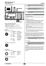
Activating setting mode
After the system start, a signal impulse (H signal 24 VDC) must be
present at the input restart interlock (pin 1) of the receiver for at least
20 seconds (pushbutton/enabling)
The 7 segment display starts with the default setting (vertical bar)
The sensors are aligned in parallel and at the same height until both
segments have reached a signal strength of 50% to 100%
With a signal impulse on the input release (pin 1) you can change be-
tween default setting and fine adjustment as long as the signal strength
is at 50% of the default setting (vertical bar)
After the setting of the sensors, the setting mode can be terminated
by the presence of a HI-signal at pin 1 for at least 25 seconds (max
6 seconds) and the actuation of the enabling button or by a voltage
reset at the receiver (+UB).
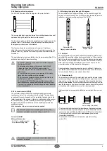
Status display
The signal strength is also shown on the display in the diagnostic win-
dow by yellow light pulses to the status light The better the alignment,
the higher the frequency of the light pulses The alignment is correct
when the light pulses switch over to continuous light
If there is no optical synchronisation between the transmitter and the
receiver, a light pulse is emitted every three seconds The setting mode
is ended by a system start ( +UB OFF/ON).
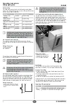
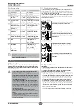
Alignment
Receiver not parallel
Both sensors parallel
b
a
b
a
Beam (a) = receive signal OK
Beam (b) = no receive signal
Beam (a) and beam (b)
= receive signals OK
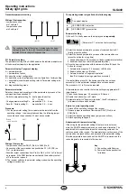
Indication basic setting
The signal strength is displayed per beam with two segments for the
first (a) and the last (b) beam
Status first beam (a)
Status last beam (b)
2 segments left-hand side = signal strength of the
first
beam (a)
2 segments right-hand side = signal strength of the
last
beam (b)
Signal strength (a) 25% … 50%
Signal strength (b) 0%
Signal strength (a) 50% … 100%
Signal strength (b) 0%
Signal strength (a) 50% … 100%
Signal strength (a) 25% … 50%
Signal strength (a) 50% … 100%
Signal strength (a) 50% … 100%
Inadequate alignment of the sensors
(height offset, not parallel)
Indication fine adjustment
The fine adjustment is displayed by means of up to 3 segments
(crossbars) for the best possible signal strength of all beams
Best possible signal strength
Signal strength for normal operation OK
- Signal strength is sufficient, if one or more beams in the
protection zone are covered (object blanking)
- Signal strength insufficient, when no beams are covered
The availability of the system is also assured if due to soiling
or operation at nominal range the best possible signal
strength (3 segments)is not reached
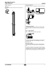
3.5 Safety distance
The safety distance is the minimum distance between the SLG440 and
the hazardous point, which must be observed in order to ensure that
the hazardous point can only be reached after the hazardous
movement has come to standstill
The protection using individual beams must be chosen so
that bodies or body parts larger than the selected resolution
(beam di beam diameter 10 mm) of the SLG440 are
detected
Calculation of the safety distance to EN ISO 13855 & EN ISO 13857
The safety distance depends on the following elements:
• Stopping time of the machine (calculation by run-on time measure
-
ment)
• Response time of the machine and the safety light grid and the down
-
stream relay (entire safety guard)
• Approach speed
• Resolution of the safety light grid


