


3
RSS36-AS
Operating instructions
Safety sensor
EN
AS-i inputs:
- Channel 1:
Data bits DI 0/DI 1 = dynamic code transmission
- Channel 2:
Data bits DI 2/DI 3 = dynamic code transmission
Databits condition static 0 or
dynamic code transmission
AS-i Outputs:
- DO 0 ... DO 3:
no Function
AS-i parameter bits:
- P0:
Actuator present
- P1:
Hysteresis signal (FID)g
- P2:
Tamper protection time active (FID)
- P3:
Device error (FID)
Actuator detection (AD):
- P0 … P3:
Actuator number 0, 01 - 15
Parameter request:
default value parameter request "1111" (0xF)
AS-i Input module address:
0
- preset to address 0, can be changed through
AS-interface bus master or hand-held programming device
LED switching conditions display:
green/red LED (AS-i Duo LED):
Supply voltage /
communication error /
slave address = 0 /
periphery error detected /
Tamper protection time active
Yellow LED:
device condition (enabling status) /
hysteresis signal / device error
For use in NFPA 79 Applications only. Only for use in
Pollution Degree 2 Environment. Adapters providing field
wiring means are available from the manufacturer.
Refer to manufacturers information.
This device complies with part 15 of the FCC Rules and Industry
Canada license-exempt RSS standard(s).
Operation is subject to the following two conditions:
(1) This device may not cause harmful interference, and
(2) this device must accept any interference received,
including interference that may cause undesired operation.
Le présent appareil est conforme aux CNR d'Industrie
Canada applicables aux appareils radio exempts de licence.
L'exploitation est autorisée aux deux conditions suivantes:
(1) l'appareil ne doit pas produire de brouillage, et
(2) l'utilisateur de l'appareil doit accepter tout brouillage
radioélectrique subi, même si le brouillage est susceptible
d'en compromettre le fonctionnement.
2.6 Safety classification
Standards:
ISO 13849-1, IEC 61508
PL:
e
Control Category:
4
PFH:
≤ 5.13 x 10
-10
/ h
PFD:
≤ 9.0 x 10
-5
SIL:
suitable for SIL 3 applications
Mission time:
20 years
3. Mounting
3.1 General mounting instructions
Please observe the relevant requirements of the standards
ISO 12100, ISO 14119 and ISO 14120.
Ensure the safety sensor and actuator is mounted on a flat surface. The
universal mounting holes provide for a variable mounting by means of M4
screws (tightening torque 2.2 … 2.5 Nm).
The component can be mounted in any position. The labelled surfaces
of the safety sensor and the actuator have to be opposite. The safety
sensor must only be used within the assured switching distances ≤ s
ao
and ≥ s
ar
.
The actuator must be permanently fitted to the safety guards
and protected against displacement by suitable measures
(e.g. tamperproof screws, gluing, drilling of the screw heads).
To avoid any interference inherent to this kind of system and any
reduction of the switching distances, please observe the following
guidelines:
• The presence of metal chips in the vicinity of the sensor is liable to
modify the switching distance.
• Keep away from metal chips.
• Minimum distance 100 mm between two safety sensors
as well as other systems with same frequency (125 kHz)
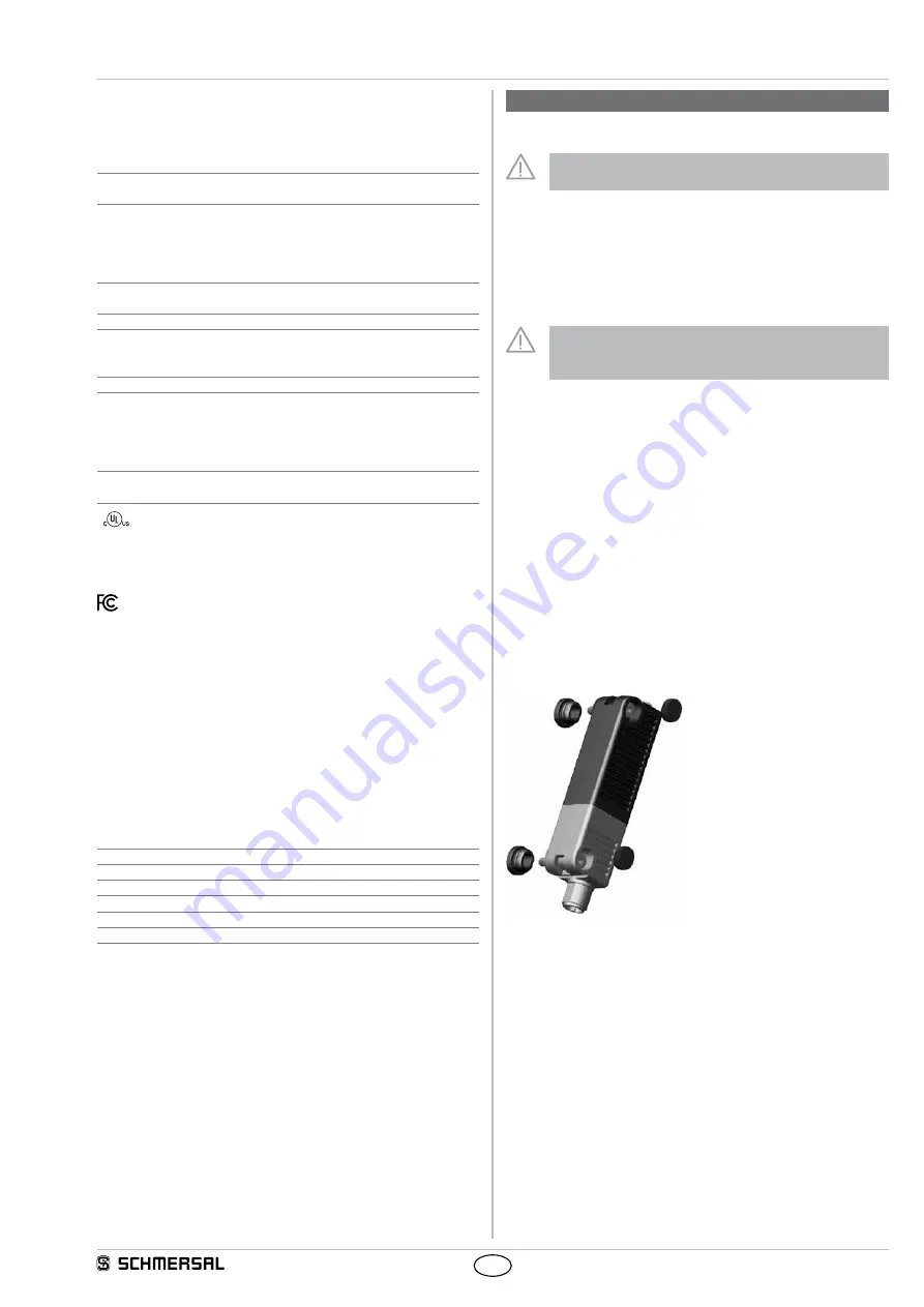
3.2 Accessories
Sealing kit
• Ordering code 101215048
• 8 plugs and 4 washers
• to seal the mounting holes and as spacer
(approx. 3 mm) to facilitate the cleaning below the mounting surface
• also suitable as tampering protection for the screw fixings.
Kit tamper-proof screws
• 4 x M4x25 incl. washers, ordering code 101217746
• 4 x M4x30 incl. washers, ordering code 101217747