


3
EBW-AZ
Operating instructions
Safety-monitoring module
EN
2.5 Safety classification
Standards:
EN ISO 13849-1, IEC 61508,
EN 60947-5-1
PL:
up to b
Control category:
up to B
DC:
< 60%
CCF:
> 65 points
SIL:
up to 1
Service life:
20 years
B
10d
value (for one channel):
Low voltages range 20%: 20,000,000
40%: 7,500,000
60%: 2,500,000
80%: 1,000,000
Maximum load 100%: 400,000
MTTF
B
d x
x
h
s/h
3600
d
10d
op
op
op
n
0,1 x n
op
t
cycle
For an average annual demand rate of n
op
= 126,720 cycles per
year, Performance Level PL e can be obtained at maximum load.
n
op
= average number of activations per year
d
op
= average number of operating days per year
h
op
= average number of operating hours per day
t
cycle
= average demand rate of the safety function in s
(e.g. 4 × per hour = 1 × per 15 min. = 900 s)
(Specifications can vary depending on the application-specific
parameters h
op
, d
op
and t
cycle
as well as the load.)
3 Mounting
3.1 General mounting instructions
Mounting: snaps onto standard DIN rails to EN 60715.
Snap the bottom of the enclosure slightly tilted forwards in the
DIN rail and push down until it latches in position.
3.2 Dimensions
All measurements in mm.
Device dimensions (H/W/D):
83 mm × 45 mm × 126.5 mm
4 Electrical connection
4.1 General information for electrical connection
The electrical connection may only be carried out by authorised
personnel in a de-energised condition.
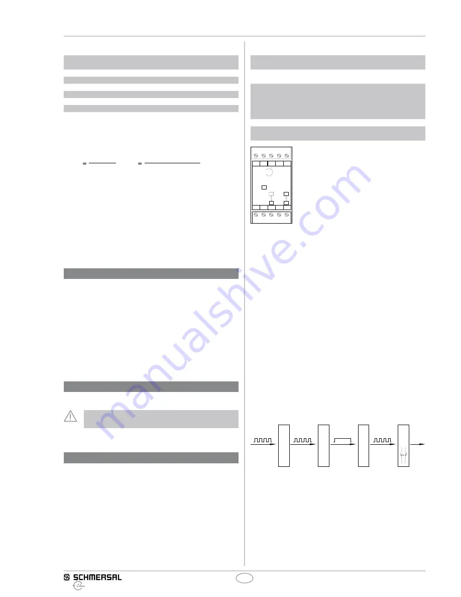
5 Operating principle and settings
5.1 LED functions
• U
B
: Status supply voltage
•
Rel.: Status switching relay K1
5.2 Description of the terminals
Voltages:
A1
A2
+24 VDC
0 VDC
Outputs:
13-14
21-22
NO-contact
NC-contact
Input sensor:
24 V
IN
0 V
TG
+24 VDC (to be used for the voltage
supply of the external sensor)
Input sensor
Sensor
Input tachogenerator
Potentiometer: Fine adjustment of the frequency
DIP switch:
DZW-SSW (possible functions rotational
speed monitor - standstill monitor)
A1 24V IN
0V
A2
13
14
21
TC
22
22
21
14
13
100%
10%
U
B
Rel.
DZW
EBW-AZ-24V
Typ:
SSW
Fig. 1
5.3 Notes
Operating principle
EBW devices detect and process signals with different quality and operating
frequency, which are prepared in the "input level" and "monitoring/
standstill detection" parts of the control. The period length of the limit
value for the control command is also set in this part of the control.
The period length of the generator signals is continuously compared
to the preset period length of the reference oscillator and transmitted
as dynamic signal to the output level of the EBW devices.
The operating principle of the EBW devices is based upon a real-time
measurement, i.e. the actual period length of the input signals is continu-
ously measured/counted and compared to the preset value. A control
command is given at the end of the period, during which the actual
value of a movement diverges from the upper or lower limit of the
preset limit value.
For the standstill signal setting, a suitable limit value must be determined
in terms of a relative standstill, i.e. the residual movement, which remains
below the limit value, still must have come to an absolute standstill or a
hazard-free situation under observance of an access speed of 1.6 m/sec.
1)
a)
b)
2)
c)
d)
3)
e)
f)
4)
g)
h)
Fig. 2: single-channel mouvement monitor EBW
1) Input level
a) Signal preparation
b) Generator adjustment
2) Monitoring
c) Period length setting
d) Fine adjustment
3) R-C oscillator
e) Signal conversion
f) static/dynamic
4) Output level
g) Converter/Relay
h) Output