


5
CSS 34
Operating instructions
Safety sensor
EN
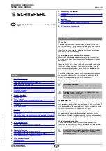
Actuation from side
The side allows for a maximum height misalignment (X) of sensor
and actuator of 36 mm (e.g. mounting tolerance or due to guard door
sagging). Increased misalignment, max. 53 mm, possible when the
CST 34-S-2 actuator is used. The axial misalignment (Y) is max. ± 10
mm.
Maximum misalignment from front
Z
Actuation from front
The front face allows for an axial misalignment
(Z) of max. ± 8 mm.
3.5 Adjustment
The distance between the sensor and the actuator must be set to < S
ao
.
If variations in the clearance between the sensor and the actuator is
detected (e.g. sagging of a safety guard), this distance must be reduced
by 4 mm. The yellow LEDs and the diagnostic output indicate the
different ranges.
Recommended Adjustment
Align the safety sensor and actuator at a distance of 0.5 x s
ao
.
The correct functionality of both safety channels must be checked by
means of the connected safety-monitoring module.
4. Electrical connection
4.1 General information for electrical connection
The electrical connection may only be carried out by
authorised personnel in a de-energised condition.
The power supply for the safety sensors must provide protection
against permanent over-voltage. Under fault conditions, the voltage
must not exceed 60 V. supply units according to IEC 60204-1 is
recommended.
The safety outputs can be integrated into the safety circuit of the control
system. For applications of PL e / control category 4 to ISO 13849-1,
the safety outputs of the safety sensor or sensor of the chain must be
wired to a safety monitoring module of the same control category .
Requirements for the connected safety-monitoring module
• Dual-channel safety input, suitable for p-type safety sensors with NO
function.
• Digital inputs to EN 61131-2, Table "Standard operating ranges for
digital inputs (current sinking)"
The safety sensors cyclically switch off the output to test them. The
switch-off times of max. 500 μs must be tolerated by the evaluating
device. Short-circuit recognition by the evaluation is not necessary.
Note on the total length of a safety sensor chain, refer to paragraph
"Series-wiring". The maximum load current of 250 mA per safety
channel must be observed. Contactors with higher load currents must
be controlled by intermediate control relays.
Information for the selection of suitable safety-monitoring
modules can be found in the Schmersal catalogues or in the
online catalogue on the Internet: www.schmersal.net.
The self-monitoring safety sensors of the CSS 34F0 or CSS 34F1
series can replace the safety-monitoring module. Therefore, they can
only be used as the first sensor of a series-wired sensor chain. (refer to
operating instructions CSS 34F0 / CSS 34F1).
If the safety sensor is connected to electronic safety-
monitoring modules, we recommend that you set a
discrepancy time of 100 ms. The safety inputs of the safety-
monitoring module must be able blanking a test impulse of
approx. 1 ms. The safety-monitoring module does not need to
have a cross-wire short monitoring function, if necessary, the
cross-wire short monitoring function must be disabled.
4.2 Series-wiring
Series-wiring can be set up. The number of devices is limited for safety
reasons. Series-wiring of CSS 34-…-SD with serial diagnostics is
possible for up to 31 devices. A 200 m long sensor chain can be set up.
Please note that voltage losses could occur (due to cable length, cable
section, voltage drop/sensor)! For longer cable lengths, the section of
the connecting cables must be taken as large as possible.
Wiring examples for series-wiring, refer to appendix.
Protection is not required when pilot wires are laid. The cables however
must be separated from the supply and energy cables. The max. fuse
rate for a sensor chain depends on the section of the connecting cable
of the sensor.
Cable design in case of serial diagnostics
The wiring capacitance of the connecting cable of the safety sensor
must not exceed 50 nF.
Depending on the strand structure, normal unshielded 30 m long control
cables LIYY 0.25 mm
2
to 1.5 mm
2
have a wiring capacitance of approx.
3 … 7 nF.
When wiring SD devices, please observe the voltage drop
on the cables and the current carrying capacity of the
individual components.
Accessories for the series-wiring
For convenient wiring and series-wiring of SD components,
the SD junction boxes PFB-SD-4M12-SD (variant for the
field) and PDM-SD-4CC-SD (variant for control cabinet on
carrier rail) are available along with additional comprehensive
accessories. Detailed information is available on the Internet,
www.schmersal.net.


