


2
Operating instructions
Safety sensor
BZ 16
EN
1.6 Warning about misuse
In case of inadequate or improper use or manipulations of the
safety switchgear, personal hazards or damages to machi
-
nery or plant components cannot be excluded. The relevant
requirements of the standard EN 1088 must be observed.
1.7 Exclusion of liability
We shall accept no liability for damages and malfunctions resulting from
defective mounting or failure to comply with this operating instructions
manual. The manufacturer shall accept no liability for damages resul-
ting from the use of unauthorised spare parts or accessories.
For safety reasons, invasive work on the device as well as arbitrary re
-
pairs, conversions and modifications to the device are strictly forbidden;
the manufacturer shall accept no liability for damages resulting from
such invasive work, arbitrary repairs, conversions and/or modifications
to the device.
2 Product description
2.1 Ordering code
This operating instructions manual applies to the following types:
BZ 16-
➀ ➁
No.
Option
Description
➀
11
1 NO contact / 1 NC contact
02
2 NC contacts
➁
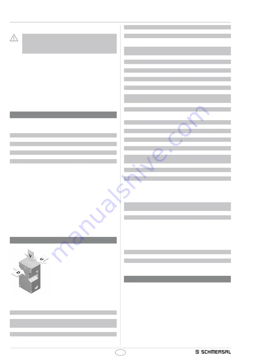
Actuating planes:
D
cover-side
U
bottom
V
front side
2.2 Special versions
For special versions, which are not listed in the order code below 2.1,
these specifications apply accordingly, provided that they correspond to
the standard version.
2.3 Destination and use
The safety sensor is designed for application in safety circuits and is
used for monitoring the position of movable safety guards to EN 1088
and IEC 60947-5-3. To actuate the safety sensors, only the BZ 16-B1
actuator can be used, conventional magnets are not suitable.
The safety switches are used for applications, in which the hazardous
situation is terminated without delay when the safety guard is opened.
Actuating planes
2.4 Technical data
Standards:
IEC 60947-5-3, BG-GS-ET-14
Design:
rectangular
Enclosure:
glass-fibre reinforced thermoplastic,
self-extinguishing
Protection class:
IP 67 to EN 60529
Termination:
Screw terminals
Cable section:
max. 2 x 1.5 mm
2
(including conductor ferrules)
Cable entry:
3 x M20
Operating principle:
non-contact, with coded actuator
Actuating magnet:
BZ 16-B1, coded
s
ao
:
10 mm minimum distance 2 mm in case
of approach from side
s
ar
:
20 mm (minimum distance 2 mm in case
of approach from side)
Hysteresis:
approx. 6 mm
Repeat accuracy R:
< 1 mm
I
e
/U
e
:
160 mA / 24 VDC ±15 % (polarity reversal)
No-load current:
≤ 70 mA
Max. fuse rating:
0.25 A (slow blow)
Outputs:
2 enabling paths 2 NC or 1 NC / 1 NO
Switching voltage:
max. 250 VAC
Switching current:
max. 4 A
Switching capacity:
max. 1000 W
Required short-circuit
current:
100 A
Voltage drop:
see Contact resistance
Max. fuse rating:
4 A gG D-fuse
Utilisation category:
AC-15: 230 V / 3 A
DC-13: 24 V / 4 A
Power consumption:
< 4 W
U
i
:
250 VAC
Overvoltage category:
III
Degree of pollution:
3
U
imp
:
4 kV
Max. switching frequency:
1 Hz
Duration of risk:
< 200 ms
Ambient temperature:
0 °C … + 55 °C
Storage and transport
temperature:
- 20 ºC … + 70 °C
Resistance to shock:
30 g / 11 ms
Resistance to vibrations:
10...55 Hz, amplitude 1 mm
Mechanical life:
50 million operations
Contacts:
AgSnO, self-cleaning, positive drive
Contact resistance:
100 mΩ in new state
2.5
Safety classification
Standards:
EN ISO 13849-1, EN 62061,
IEC 60947-5-3
PL:
up to e
Control category:
up to 4
PFH value:
4.73 x 10
-8 /
h
Applicable for applications with up to max.
100,000 switching cycles/year (NC/NC
version) or 50,000 switching cycles/year
(NO/NC version) and with max. 250 mA
contact load. Diverging applications upon
request.
SIL:
up to 3
Service life:
20 years
Classification:
PDF-M
3 Mounting
3.1 General mounting instructions
•
Fitting is only authorised in a de-energised condition
•
Do not use the sensor and the actuator as a mechanical backstop
• Any mounting position, provided that the active surfaces are opposite
• Inseparably fix the safety sensor and the actuator to the safety guard
(the mounting dimensions are indicated on the back of the enclosure)
• Fix the safety sensor and the actuator onto a flat surface
• Do not install the sensor and the actuator in strong magnetic fields
• If possible, do not mount the sensor and the actuator on ferromagne
-
tic material
•
Do not subject the components to extreme vibrations
•
Keep away from metal chips
•
Mounting distance between two sensors should always be at least
10 mm