4
Operating instructions
Safety switch with interlocking function
AZM 200 D
EN
3.3 Retrofit kit for Emergency release/Emergency exit
The retrofit kit is used for subsequent functional expansion of the safety
switch.
Designation
Ordering code
Emergency release
RF-AZM200-N
103003543
Emergency exit
RF-AZM200-T
103004966
71
16
4. Electrical connection
4.1 General information for electrical connection
The electrical connection may only be carried out by
authorised personnel in a de-energised condition.
The power supply of the safety switch must provide protection against
permanent overvoltage. To that effect, stabilised PELV supply units
must be used. The safety outputs can be directly integrated in the
safety circuit of the control system. For applications up to PL e / control
category 4 to ISO 13849-1, the safety outputs Y1 and Y2 of the safety
switch or safety switches must be connected to a safety-monitoring
module of the same control category (refer to wiring example).
The antivalent switching safety outputs Y3 and Y4 are suitable for
requirements up to PL d / control category 3. To that effect, the outputs
must be connected to a safety-monitoring module meeting at least the
requirements of PL d / control category 3 to ISO 13849-1. The outputs
cannot be wired in series.
Inductive loads (e.g. contactors, relays, etc.) are to be provided with
suitable interference suppression circuitry.
Requirements for the connected safety-monitoring module:
• Dual-channel safety input, suitable for 2 or 4 p-type semi-conductor
outputs
Safety outputs Y1, Y2
The safety-monitoring module must tolerate internal functional with
cyclic switch-off of the safety outputs Y1 and Y2 for max. 2 ms (typically
< 1 ms). The switch-off stage of the test cycle is temporarily reduced
by an active ohmic discharge of the cable. The safety-monitoring
module does not need to have a cross-wire short monitoring function, if
necessary, the cross-wire short monitoring function must be disabled.
Safety outputs Y3 and Y4
The safety outputs Y3 and Y4 are antivalent switching outputs.
A short concordance (< 50 ms) must be accepted, as the AZM 200 D
might present small switching delays.
Cable
If the cable input is realised through a metric M20 cable gland, this
gland must be dimensioned by the user so as to fit the cable used.
A cable gland with strain relief and suitable IP protection class must
be used.
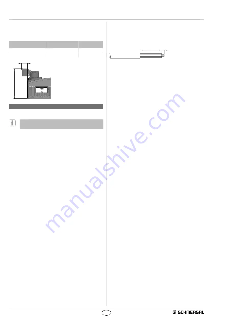
40
5
The maximum cable length is 200 m (for ST2 M12 connectors approx.
20 m depending on the cable section used for an operating current
of 0.5 A). The maximum cable section is 1.5 mm², incl. conductuor
ferrules. Prior to the connection, the cable must be stripped by
40+5 mm and insulated by 5 mm.


