


3
AES 3075
Operating instructions
Safety-monitoring module
EN
3. Mounting
3.1 General mounting instructions
Mounting: snaps onto standard DIN rails to EN 60715.
3.2 Dimensions
Device dimensions (H/W/D): 100 x 75 x 110 mm
4. Electrical connection
4.1 General information for electrical connection
The electrical connection may only be carried out by
authorised personnel in a de-energised condition.
Wiring examples: see appendix
5. Operating principle and settings
5.1 Operating principle after the operating voltage is switched on
If a safety guard is opened, the microprocessors disable the enabling
outputs and therefore the external contactors. The enabling outputs
are re-enabled, when the function of these outputs and all connected
components has been checked. During a switch-on cycle (opening and
closing of at least one safety guard), all individual faults, which could
lead to a hazardous situation, are detected at the switches, the cables
and wires as well as in the safety-monitoring module itself. This always
causes the enabling outputs and therefore the connected external
contactors as well to be disabled.
Extension of enable delay time
On safety guards with strong residual vibrations, the end position of
a non-contact position switch is often "overrun". As a result, an error
message of the safety-monitoring module is usually generated.
To avoid this, the "enabling delay time" can be extended by removing
the device cover and setting the internal bridge located in the middle of
the board (refer to "Settings" drawing).
With jumper:
enabling delay time = 1 second
Without jumper:
enabling delay time = 0.1 second
(factory setting)
Setting the contact type (S13/S14)
After removal of the enclosure cover, the contact type can be
individually set for each safety guard by means of jumpers on the board
(refer to "Settings" drawing). S21/S22 always is a NC contact.
Contact combinations
NC/NC contact
jumper inside
NO/NC contact
jumper outside (factory setting)
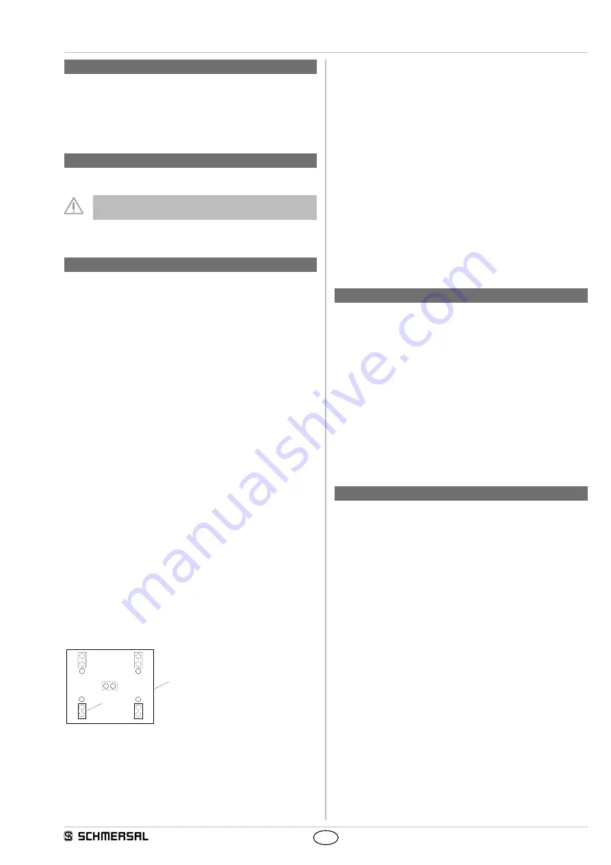
Settings
S1
S3
S2
S4
4
4
4
4
3
2
1
Key
1 Board
2 Jumper
3 Enable delay time
4 Contact type
additional transistor outputs
Y1: "high", safety guard 1 open
Y2: "high", safety guard 2 open
Y3: "high", safety guard 3 open
Y4: "high", safety guard 4 open
Y5: "high", system OK
Start function and feedback circuit of the external positive-guided
contactors X1 / X2
The series-wired NC contacts of the external contactors must be
connected to X1 (+) and X2. In addition to that, a series-wired
"pushbutton" can be used to trigger the start function.
Enabling function X3 / X4
A "switch" can be connected to the terminals X3 (+) and X4, by means
of which the enabling outputs Y14 and Y24 can be enabled or disabled
when the safety guard is closed. If this function is not used, establish a
bridge.
Outputs Y14 / Y24
6. Set-up and maintenance
6.1 Functional testing
The safety function of the safety-monitoring module must be tested.
The following conditions must be previously checked and met:
1. Correct fitting of the safety-monitoring module
2. Fitting and integrity of the power cable
6.2 Maintenance
In the case of correct installation and adequate use, the safety-
monitoring module features maintenance-free functionality.
A regular visual inspection and functional test, including the following
steps, is recommended:
• Check the correct fixing of the safety monitoring module
• Check the cable for damage.
Damaged or defective components must be replaced.
7. Disassembly and disposal
7.1 Disassembly
The safety monitoring module must be disassembled in the de-
energised condition only.
7.2 Disposal
The safety monitoring module must be disposed of in an appropriate
manner in accordance with the national prescriptions and legislations.


