

Vacuum switch
Pressure switch
VS-D
Series
BA 30.30.01.00011_EN
Status 03.2014 / Index 01
1 / 3
J. Schmalz GmbH, Aacher Straße 29, D-72293 Glatten
Tel 07443/2403-0, Fax -259
Safety
These operating instructions contain important information on
the use of vacuum switches. Please read them carefully and
keep them in a safe place for future reference.
You must read and understand these operating instructions
before connecting and using the vacuum switch.
Always comply with these instructions and observe the safety
notes and warnings.
Warnings:
The vacuum switch may not be used outside the specified
performance limits, since this can result in malfunctions and/or
destruction of the switch!
The vacuum switch may not be used in explosion-hazard areas,
since it may cause fires and explosions!
The switch may not be used for safety-relevant functions
The switch may not be opened for any purpose (including
repairs)! Opening the switch may damage it and may also result
in injuries!
The switch may be used only with
power supply units which provide
a protective low voltage (PELV) and with
reliable isolation of the supply voltage
in accordance with EN60204.
PELV
Caution:
Do not carry the vacuum switch by its cable, and do not pull the cable.
Protect the switch against mechanical interference (tearing off).
Switch off the supply voltage before connecting the switch.
Do not expose the switch to splash-water.
Never insert any objects (such as wires, tools, etc.) into the vacuum
connection of the switch.
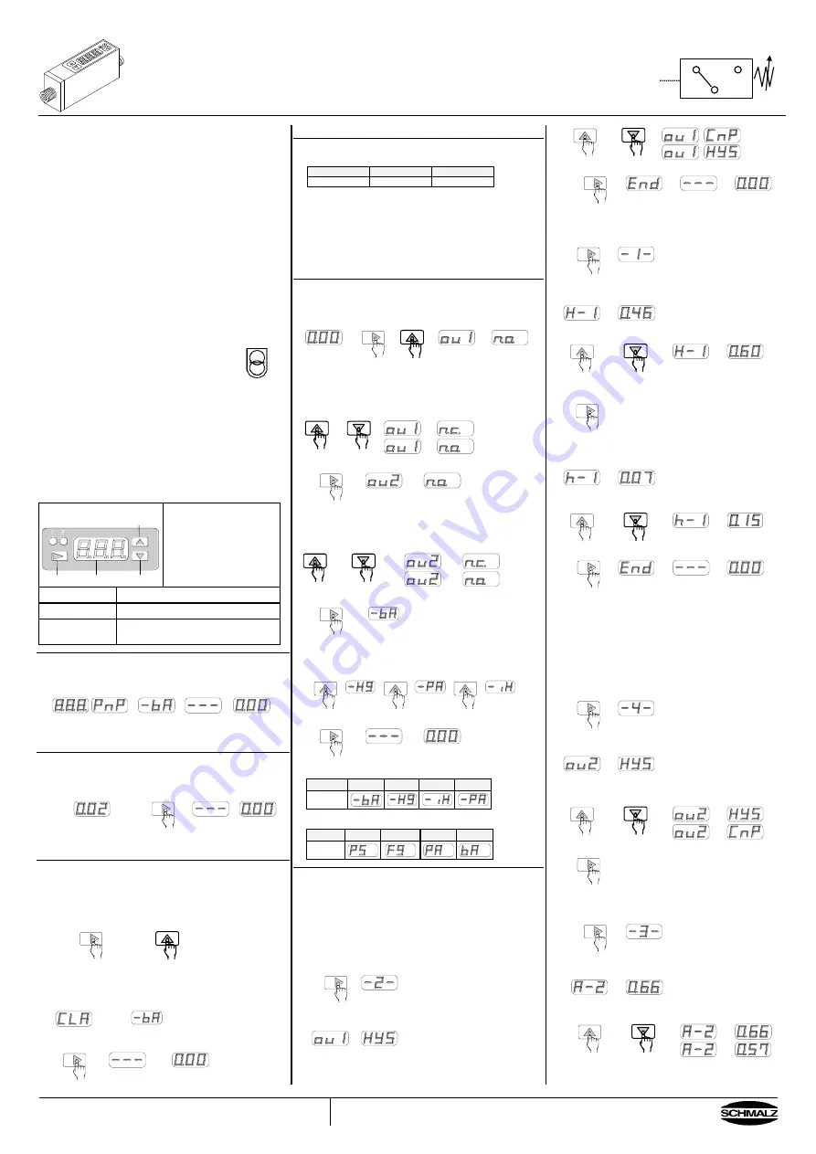
1. Front panel
LED Output 1
LED Output 2
Up
Mode
Display
Down
Display:
Preset values in setting mode.
Vacuum level in measurement
mode.
The minus sign is not
displayed when pressure
unit bar, inHg or mmHg is
selected (VS-V-D).
Mode
Button to select the different modes.
Up & Down
Buttons to change settings.
LED Output 1
and Output 2
Switching indicator,
Output 1 = red, Output 2 = green.
2. Connecting power supply in normal operation
After connecting the power supply, in the display panel you can
see the presetted values.
When connecting the power supply do not push any key.
Type
Selected
pressure unit
Display
Measured
pressure
3. Zero-point adjustment
Adjust the zero-point only when the vacuum/pressure line is not
connected. To adjust the zero-
point, push the ”Mode“-key at
least 3 seconds.
Display Measured
p
atm
Hold for
min. 3 sec
Zero-point
adjusted
4. Clear All
If the switch was wrongly programmed, it can be set back in
to the factory settings.
All stored values are cleared. To accomplish this function,
disconnect the switch from the power supply. Whilst pushing the
”Mode“-key” and the ”Up“-key, connect the power supply again.
Push and hold both keys simultaneous
After connecting the power supply, the display shows “CLA“.
When you release the buttons, the presetted pressure unit is
displayed by “ -bA” resp. ”bA”.
When pushing the ”Mode“-key one time, the selected pressure
unit is confirmed and stored.
1x
To adjust an other pressure unit see paragraph 6.3
5. Factory settings
The switch is delivered with following factory settings
Unit
Output 1
Output 2
bar
HYS, N.O.
HYS, N.O.
This setting can be changed (programmed).
The programming is described in the following paragraph.
A built-in EEPROM retains data for a period of min. 10 years.
The data are min. 10.000 times rewritable.
N.O = normally open, N.C. = normal closed,
HYS = operating mode „Hysteresis mode“
The initial settings of the operating mode is shown
in the table in paragraph 8.
6. Setting of output configuration (N.O. or N.C.) and
pressure unit (e.g. bar).
To adjust the output configuration and the pressure unit, push
and hold the ”Mode”-key, the push the “Up“-key.
hold
The display is alternating between
“ou I“ and ”n.o.”
6.1 Selection N.O. or N.C. of output 1
To change the setting, push ”Up”- or “Down”-key.
Store the settings with the
“Mode”-key
1x
Now the display switches to the selection of output 2,
the display changes from ”ou 2” to ”n.o.”
6.2 Selection N.O. or N.C. of output 2
To change the setting,
push ”Up”- or “Down”-key.
Store the settings with the “Mode”-key.
1x
bar
Now the display switches to the selection of the pressure unit.
6.3 Adjust the pressure unit
To change the setting, push ”Up”- or “Down”-key.
mmHg
kPa
inHg
Store the settings with the “Mode”-key.
1x
Possible pressure units for VS-V-D
Unit
bar
mmHg
inHg
kPa
Symbol
Possible pressure units for VS-P10-D
Unit
psi
kgf/cm²
MPa
bar
Symbol
7. Adjusting the operating mode
7.1 Adjusting output 1
Example:
Switch VS-V-D, output 1 has the operating mode
“Hysteresis-mode“.
switching point:
-0,6 bar
hysteresis:
0,15 bar
Further information to the modes see paragraph 8.
Adjusting the operating mode
To select output 1, push ”Mode”-key 2x.
2x
wait 2 sec
After 2 seconds, the display is alternating between “ou I“
and the preadjusted operating mode.
Push the ”Up”- or “Down”-key until “HYS“ for the desired
switching mode „Hysteresis-mode“ is displayed.
Store the settings with the “Mode”-key.
1x
Setting switching point and hysteresis
To select the switching point of output 1 push ”Mode”-key 1x.
1x
wait 2 sec
After 2 seconds, the display is alternating between “H-1“
and the preadjusted value.
To adjust the switching point, push the ”Up”- or “Down”-key
until the desired value is displayed.
Store the settings with the “Mode”-key.
1x
Now the display switches to the selection of the hysteresis.
The display is alternating between “h-1“ and the preadjusted
value.
To adjust the hysteresis, push the ”Up”- or “Down”-key until
the desired value is displayed.
Store the settings with the “Mode”-key
1x
7.2 Adjusting output 2
Example:
Switch VS-V-D, output 2 has the operating mode
“Window comparator mode“
Switching points are between -0,57 bar and -0,83 bar
(lower margin A=-0,57, upper margin b = -0,83)
Further information to the modes see paragraph 8.
Adjusting the operating mode
To select output 2, push ”Mode”-key 4x
4x
wait 2 sec
After 2 seconds, the display is alternating between
“ou 2“ and “HYS“.
Push the ”Up”- or “Down”-key until “CnP“ for the desired
switching mode “Window Comparator Mode“ is
displayed.
Store the settings with the “Mode”-key.
1x
Adjusting the lower and the upper margin
To select the lower margin of output 2, push ”Mode”-key 3x
3x
wait 2 sec
After 2 seconds, The display is alternating between “A-2“
and the preadjusted value.
Push the ”Up”- or “Down”-key until the desired value is
displayed.
Store the settings with the “Mode”-key.


