Connection module WL (wireless)
Art.-No. BTEAR2WL
BTEAR6WL
Operating instructions
Страница 1: ...Connection module WL wireless Art No BTEAR2WL BTEAR6WL Operating instructions ...
Страница 2: ...s applicable at the installation site of the product 2 Information on safety 2 1 Safety messages and hazard categories These operating instructions contain safety messages to alert you to potential hazards and risks In addition to the instructions provided in these operating instructions you must comply with all directives standards and safety regulations applicable at the installation site of the...
Страница 3: ...icable at the installation site of the product 2 3 Predictable incorrect application The product must never be used in the following cases and for the following purposes Hazardous area EX If the product is operated in hazardous areas sparks may cause deflagrations fires or explosions In conjunction with products which are used for health saving or life saving purposes or whose operation may incur ...
Страница 4: ...ith the specified ambient conditions during transport or storage of the product Use the original packaging when transporting the product Store the product in a clean and dry environment Verify that the product is protected against shocks and impact during transport and storage Failure to follow these instructions can result in equipment damage 4 4 1 ...
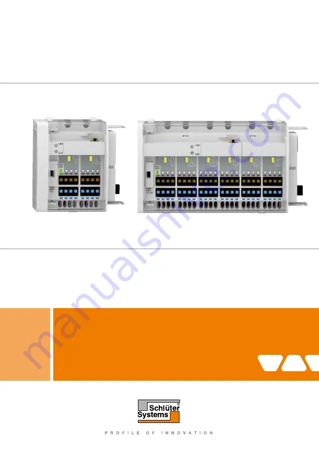
Страница 5: ...bung 1 Übersicht A Anschlussmodul WL EAR2WL B Anschlussmodul WL EAR6WL C Abschlusskappe 1 Anlerntasten LRN Taste 2 Verriegelung 3 Betrieb Netzspannung LED grün 4 Thermischer Stellantrieb aktiv LED gelb 5 Anschlussmodul WL Antennen anschlussleiste für thermische Stellantriebe 6 Sicherungsfach 7 Resettaste CLR Taste 4 4 5 4 2 7 6 2 7 4 3 2 1 A 5 2 3 1 6 C B 8 8 4 4 5 4 2 7 6 2 7 4 3 2 1 A 5 2 3 1 6 ...
Страница 6: ...at cool The product with 2 or 6 independent control circuits controls the thermal actuators via the signals of the room sensors and the base module Control Multiple products with 2 or 6 control circuits can be installed adjacent to each other The room sensors transmit the actual temperature and the reference temperature directly to the product via wireless EnOcean technology 4 5 Approvals conformi...
Страница 7: ... WL only 0 3 W 0 5 W Fuse for thermal actuators T 1 A T 3 15 A Permissible cable type to thermal actuators H03 VV H2 F 2 x 0 75 mm H03 VV H2 F 2 x 0 75 mm The following components may be connected to one product Room sensors max 2 max 6 Thermal actuators max 8 max 24 Electrical safety Protection class II EN 60730 1 II EN 60730 1 Degree of protection IP 20 EN 60529 IP 20 EN 60529 Electromagnetic co...
Страница 8: ...ating circuit manifold 5 1 Mounting the product Verify that the product is disconnected from mains 2 Pull off the end cover 3 Connect the connection module WL connection module s to the base module Control 1 Open the cover using a screwdriver 4 Push down the two catches ...
Страница 9: ...9 GB 5 Fit the end cover onto the last connection module WL connection module 6 Refit the cover and close it Click ...
Страница 10: ... ELECTRIC SHOCK Verify that the degree of protection against electric shock protection class double insulation is not reduced by the type of electrical installation Failure to follow these instructions will result in death or serious injury DANGER ELECTRIC SHOCK CAUSED BY LIVE PARTS Disconnect the mains voltage supply before performing the work and ensure that it cannot be switched on Verify that ...
Страница 11: ...ough the strain reliefs A and connect the wires to the corresponding terminals observe colour coding 1 Fix the cable at the rear of the connection module WL connection module using the cable clamp A 2 Push the stripped wires all the way into the terminals 3 If the stripped wires do not easily push into the terminals then press the catch B to open the terminal Catch B should also be pressed to disc...
Страница 12: ...s 3 It is possible to open the cable clamps To do so pull the two tabs B outwards and remove the cable clamp 5 3 Mounting modules on a DIN rail B B Verify that all modules base module Control and connection modules WL are plugged together and firmly locked B B Verify that all cables are connected 1 Fit the modules into the DIN rail with the upper hooks 2 Push the lower end of the modules towards t...
Страница 13: ...13 GB 1 Slightly lift the modules 2 Tilt the top away from the DIN rail 3 Remove the connected modules towards the bottom 5 4 Removing modules from a DIN rail ...
Страница 14: ...position of the antenna mount it temporarily using for example removable adhesive tape 4 Close the cover of the cabinet 5 Set all room sensors to maximum temperature 6 Wait at least one minute after having set the last room sensor to maximum temperature 7 Open remove the cover All control circuits must be in heating mode The yellow LEDs light 8 Close the cover 9 Set all room sensors to minimum tem...
Страница 15: ...e DIN rail 1 Apply mains voltage The green LEDs operation of the base module Control and of the product light up 6 2 Connecting room sensors WL to the product 6 2 1 Preparation B B Verify that the single room temperature controller is in operation and that the cover of the product has been removed B B Verify that the room sensors WL to be used have been exposed to sunlight for at least one day or ...
Страница 16: ...ain within the next 30 seconds the programming process is cancelled Cancellation of the programming is indicated by the yellow LED not being lit for four seconds 5 After successful programming cancellation of programme the yellow LED flashes at intervals of one second 6 Press the LRN key of the product for at least 0 5 seconds to contin ue with the next control circuit in programming mode 7 You no...
Страница 17: ...ule WL to which the room sensor WL is connected 3 Verify that the room sensor WL being tested is connected to the correct control circuit 4 Repeat this procedure for all other room sensors Betrieb DE Betrieb Übersicht der LED Signale Anzeige Zustand Erklärung A Betrieb AC 230 V LED grün Leuchtet Wenn Netzspannung für die Thermischen Stellantriebe vorhanden ist Erlischt Bei Ausfall der Netzspannung...
Страница 18: ...supply voltage Fuse defective Check the fuse LED 5 V operation not lit green LED No mains voltage Check the supply voltage Fuse defective Check the fuse Other malfunctions Power supply unit defective Contact your specialised company 1 Open the cover using a screwdriver Example Replacing the fuse in the base module Control 2 Remove the fuse holder 3 Replace the defective fuse with a G fuse insert 5...
Страница 19: ... Overview fuse types 10 Decommissioning disposal Dispose of the product in compliance with all applicable directives standards and safety regulations Electronic components must not be disposed of together with the normal household waste 1 Disconnect the product from mains 2 Dismount the product see chapter Mounting reverse sequence of steps 3 Dispose of the product 11 Warranty See our terms and co...
Страница 20: ... Fax 44 1530 813376 sales schluter co uk www schluter co uk 12 Spare parts and accessories NOTICE DAMAGE DUE TO UNSUITABLE PARTS Only use genuine spare parts and accessories provided by the manufacturer Failure to follow these instructions can result in equipment damage Product Product designation Art No Figure Connection module EAR2WL BTEAR2WL Connection module EAR6WL BTEAR6WL Spare parts and acc...