

390G+ INSTALLATION INSTRUCTIONS
3
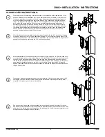
Prep the gate and post according to the instructions or in accordance with the requirements of the sit-
uation. Note that some installations may require additional brackets, hardware, or reinforcement for a
sound installation. Install the armature housing to the upper TJ bracket using the two #6-32 flat head
machine screws. Do not remove the foam rubber compression pads. Install the armature to the upper
TJ bracket using the tapered washer, external tooth washer and flat washer. Note that the tapered
washer assembles with the pointed side toward the armature, then the external tooth washer, followed
by the flat washer. Pre assemble the armature assembly to the upper TJ bracket as shown (right)
using the 1/4-20 button head socket cap screws and washers. Do not completely tighten them at this
time.
Loosen the socket cap screws which secure the standard mounting
bracket to the magnetic lock assembly and remove the bracket. (The
socket head cap screws are captured in the magnetic lock assembly.)
Slide the TJ mounting plate into the magnetic lock assembly, leaving the
upper two holes exposed. Place magnet/bracket assembly onto gate post
and secure using two of either #10 flat head self tapping screws or the
10-24 flat head machine screws. Slide the magnetic lock upward to
expose the to lower holes. Fasten the assembly with the remaining two
#10 screws. Center the assembly on the TJ mounting plate and lock into
place using two 6-32 set screws. A rubber mallet may be used to adjust
position if tight. Fasten thestandard mounting plate to the magnetic lock
using the 3/16 hex wrench provided.
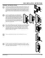
Mount armature/TJ bracket assembly to moving part of gate using four of either #10 flat head self tap-
ping screws or the 10-24 flat head machine screws. Close the gate and secure it (if such mechanical
means exists). With the gate in its closed position, push the armature/upper TJ bracket assembly
toward the armature so that it comes to rest completely engaged, with no air gap. (If a temporary
power supply is available to power up the lock do so in order to ensure that the lock will properly
engage.) Mark the position of the armature/upper TJ bracket assembly (relative to the lower TJ
assembly.) Open the gate. Tighten the1/4-20 button head socket cap screws completely. Secure the
position with the remaining 1/4-20 set screw.
Slide the dress plate into the lower TJ bracket. Center it and secure with a 6-32 set screw.
Run conduit to lock and make wiring connections for the voltage being used. See page 1 for wiring
and monitor switch information. If the lock is used in a particularly corrosive environment such as near
salt water or in a climate where salt is applied on the roads apply a thin film of grease (supplied) to the
mating surfaces of the magnet and the armature.
SWINGING GATE INSTRUCTIONS:
4.
5.
3.
2.
1.
FORM 39080 REV. E
1/2010


