Operation
P746/EN
OP/G31
MiCOM P746
(OP) 5-
7
OP
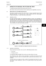
The check zone is the sum of all the current nodes entering and leaving the substation
(feeders).
Scheme differential current = sum of all differential current feeder nodes:
i
diff
(t) CZ =
⏐Σ
i
diff
⏐
The Check Zone will operate as the Zone element.
1.2.4 Tripping
Criteria
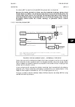
A trip signal for a zone will be issued:
1.
If the fault is detected in the zone AND
2.
confirmed by the check zone AND
3.
confirmed by the phase comparison.
For a fault to be detected, 4 trip criterions and 4 (optional) must be met; these criterions are:
For the Zone:
•
If 2 consecutive calculations are above (ID>2) and k × Ibias
•
Confirmation of the phase comparison algorithm
•
Optional Voltage criteria (U< or V1< or V2> or 3V0>)
For the Check Zone:
•
If 2 consecutive calculations are above (IDCZ>2) and kCZ × Ibias
1.2.5
Current Circuit Supervision
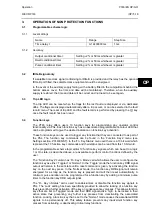
During normal operation the differential current in the scheme should be zero or negligible.
Any anomaly is detected via a given threshold
I
D
>1.
A biased differential element is used to supervise the current circuit. A differential current will
result if the secondary circuit of a CT becomes open circuited, short circuited; the amplitude
of this current is proportional to the load current flowing in the circuit monitored by the faulty
current circuit.
The setting is chosen to be as low as possible (minimum suggested setting is 2% of the
biggest CT primary winding) but also allow for standing differential current for example due
to CT mismatch and varying magnetising current losses. 5 to 20% is a typical application
range.
The element is typically time delayed for 5 seconds (set greater than the maximum
clearance time of an external fault). Instead the time delay allows the relevant protection
element (which should be substantially faster) to clear the fault instead i.e.
I
D
>2 in the case
of an internal phase fault.
1.3 Additional
protection
1.3.1
Dead Zone protection (DZ)
On a feeder, if the isolators or the breaker is open, a dead zone (or end zone) is said to exist
between the open element and the CT. The P746 can protect this zone with the Dead Zone
protection. This is a simple time delayed overcurrent and earth fault element which is only
active when a dead zone is identified in the local topology.
Содержание MiCOM P746
Страница 4: ......
Страница 5: ...Pxxx EN SS G11 SAFETY SECTION...
Страница 6: ......
Страница 8: ...Pxxx EN SS G11 Page 2 8 Safety Section BLANK PAGE...
Страница 16: ...P746 EN IT G31 Introduction MiCOM P746...
Страница 18: ...P746 EN IT G31 Introduction IT 1 2 MiCOM P746 IT BLANK PAGE...
Страница 26: ...P746 EN TD G31 Technical Data MiCOM P746...
Страница 38: ...P746 EN GS G31 Getting Started MiCOM P746...
Страница 78: ...P746 EN ST G31 Getting Started MiCOM P746...
Страница 80: ...P746 EN ST G31 Settings ST 4 2 MiCOM P746 ST BLANK PAGE...
Страница 112: ...P746 EN ST G31 Settings ST 4 34 MiCOM P746 ST BLANK PAGE...
Страница 114: ...P746 EN OP G31 Operation MiCOM P746...
Страница 136: ...P746 EN OP G31 Operation OP 5 22 MiCOM P746 OP BLANK PAGE...
Страница 138: ...P746 EN AP G31 Application Notes MiCOM P746...
Страница 142: ...P746 EN AP G31 Application Notes AP 6 4 MiCOM P746 AP BLANK PAGE...
Страница 194: ...P746 EN AP G31 Application Notes AP 6 56 MiCOM P746 AP BLANK PAGE...
Страница 196: ...P746 EN PL G31 Programmable Logic MiCOM P746...
Страница 238: ...P746 EN MR A11 Measurements and Recording MiCOM P746...
Страница 240: ...P746 EN MR A11 Measurements and Recording MR 8 2 MiCOM P746 MR BLANK PAGE...
Страница 258: ...P746 EN FD G31 Firmware Design MiCOM P746...
Страница 280: ......
Страница 342: ...P746 EN CM F21 Commissioning and Maintenance CM 10 62 MiCOM P746 CM Commissioning Engineer Customer Witness Date Date...
Страница 348: ...P746 EN MT A11 Maintenance MiCOM P746...
Страница 350: ...P746 EN MT A11 Maintenance MT 11 2 MiCOM P746 MT BLANK PAGE...
Страница 364: ...P746 EN MT A11 Maintenance MT 11 16 MiCOM P746 MT BLANK PAGE...
Страница 366: ...P746 EN TS G31 Troubleshooting MiCOM P746...
Страница 368: ...P746 EN TS G31 Troubleshooting TS 12 2 MiCOM P746 TS BLANK PAGE...
Страница 382: ...P746 EN SC G31 SCADA Communications MiCOM P746...
Страница 424: ...P746 EN SC G31 SCADA Communications SC 13 42 MiCOM P746 SC BLANK PAGE...
Страница 426: ...P746 EN SG F21 Symbols and Glossary MiCOM P746...
Страница 438: ......
Страница 440: ...P746 EN IN G31 Installation IN 15 2 MiCOM P746 IN BLANK PAGE...
Страница 465: ...Installation P746 EN IN G31 MiCOM P746 IN 15 27 IN 10P74611 1 FIGURE 18 MiCOM P746 80TE WIRING DESCRIPTION P746xxxL...
Страница 468: ......
Страница 470: ...P746 EN HI G31 Remote HMI HI 16 2 MiCOM P746 HI BLANK PAGE...
Страница 500: ...P746 EN HI G31 Remote HMI HI 16 32 MiCOM P746 HI BLANK PAGE...
Страница 502: ......
Страница 504: ...P746 EN CS A11G31 Cyber Security CS 17 2 MiCOM P746 CS BLANK PAGE...
Страница 524: ...P746 EN VH G31 Firmware and Service Manual Version History MiCOM P746...
Страница 529: ......


