Schaub Lorenz SL0520KO Скачать руководство пользователя страница 65

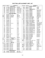
ELECTRICAL REPLACEMENT PARTS LIST

REF. NO.

PART NO.

DESCRIPTION

REF. NO.

PART NO.

DESCRIPTION

TRANSISTORS

P.C.BOARD ASSEMBLIES

Q4002

TCAT032034

TRANSISTOR, SILICON

KTC3203_Y-AT

PCB010

A5E528C010

PCB ASS'Y

VMB290B

Q4005

TPAAC05002 COMPOUND TRANSISTOR

KRA103SRTK

PCB020

A5E503C020

PCB ASS'Y

VPA150A

Q4006

TCATC31980 TRANSISTOR,SILICON

KTC3198-AT(Y,GR)

PCB110

A5E529C110

PCB ASS'Y

TCB419B

Q4007

TCATC31980 TRANSISTOR,SILICON

KTC3198-AT(Y,GR)

PCB340

A5E528C340

PCB ASS'Y

TEBB08B

Q4106

T6YJ1037K0

TRANSISTOR,SILICON

2SA1037AKT146R,S

MISCELLANEOUS

Q4107

TCAA3875SY TRANSISTOR SILICON

KTC3875S_Y_RTK

B502

024HT03563

CORE,BEADS

W4BRH3.5X6X1.0X2

Q4118

TCAA3875SY TRANSISTOR SILICON

KTC3875S_Y_RTK

B505

024HT03563

CORE,BEADS

W4BRH3.5X6X1.0X2

Q4202

T6YJ1037K0

TRANSISTOR,SILICON

2SA1037AKT146R,S

B602

024HT03564

CORE,BEADS

W4BRH3.5X6X1.0

Q4205

TCAA3875SY TRANSISTOR SILICON

KTC3875S_Y_RTK

B1001

024HT03553

CORE,BEADS

W5RH3.5X5X1.0

Q4207

TCAA3875SY TRANSISTOR SILICON

KTC3875S_Y_RTK

B1002

024HT03553

CORE,BEADS

W5RH3.5X5X1.0

Q4210

TCAA3875SY TRANSISTOR SILICON

KTC3875S_Y_RTK

B2201

024HT03553

CORE,BEADS

W5RH3.5X5X1.0

COILS &TRANSFORMERS

B2202

024HT03553

CORE,BEADS

W5RH3.5X5X1.0

L401

021679472K

COIL

4.7   MH

B2203

024HT03553

CORE,BEADS

W5RH3.5X5X1.0

L402

022800033A

COIL,LINEARITY

20416A

B4001

024HT03553

CORE,BEADS

W5RH3.5X5X1.0

  ! L501

029T0000A1

COIL,LINE FILTER

0R7A223F24

B4201

024HT03564

CORE,BEADS

W4BRH3.5X6X1.0

  ! L502

029T000092

COIL,LINE FILTER

1R0A103F24

B4202

024HT03564

CORE,BEADS

W4BRH3.5X6X1.0

  ! L503

028R200015

COIL,DEGAUSS

8R200015

BT101

1412004008

BATTERY,MANGAN

R03(AB)E_2P_G

L504

02AHB0A0A4 CORE,FERRITE

W5T_20*10*10A

BT102

1412004008

BATTERY,MANGAN

R03(AB)E_2P_G

L602

021375101K

COIL

100   UH

CD302

06CU12414A

CORD CONNECTOR

CU12414A

L603

0216A6680K

COIL

68    UH

CD401

06CU251201

CORD CONNECTOR

CU251201

L604

021673101K

COIL

100   UH

  ! CD501

1206459803

CORD AC BUSH

6459803

L605

0216S12R2J

COIL

2.2   UH

CD502

06CUU23001

CORD CONNECTOR

CUU23001

L606

0216A62R2K

COIL

2.2   UH

CD602

06CH01388A

CORD EIS CONNECTOR

CH01388A

L607

0216A62R2K

COIL

2.2   UH

CD801

06CU823001

CORD CONNECTOR

CU823001

L608

0216A6180K

COIL

18    UH

CD851

06CU2B1201

CORD CONNECTOR

CU2B1201

L610

021673101K

COIL

100   UH

CD852

WDL6040038 FLAT CABLE AWM2468

AWG26 6C BLACK 400MM

L611

021673101K

COIL

100   UH

CD853

WCL6836038 FLAT CABLE AWM2468

AWG26  5C GRAY  360MM

L612

033700005R

COIL,VIDEO IFT

3700005

CF601

1022038R9E

FILTER,SAW

SAFGP38M9VAKZ00B

L613

02167F101J

COIL

100   UH

CF603

1012T04001

FILTER,CERAMIC TRAP

MKT40.4MA110P-TF

L614

0216A6100K

COIL

10    UH

CF605

1012T5R513

FILTER,CERAMIC TRAP

TPSRA5M50B00-A0 or

L1001

0216A6120K

COIL

12    UH

1012T5R503

FILTER,CERAMIC TRAP

TPS5.5MB-TF21

L1002

0216A6100K

COIL

10    UH

CP302

069W120029

CONNECTOR PCB SIDE

TID-X02P-M1

L1202

02167F100J

COIL

10    UH

CP402

069S450089

CONNECTOR PCB SIDE

A1561WV2-A5P

L1203

02167F100J

COIL

10    UH

CP501

069S320419

CONNECTOR PCB SIDE

A3963WV2-3PD

L1204

02167F101J

COIL

100   UH

CP502

069S420110

CONNECTOR PCB SIDE

A1561WV2-2P

L4003

031616003R

COIL,BIAS OSC

1616003

CP603

069X160379

CONNECTOR PCB SIDE

06JQ-ST

L4005

02167F101J

COIL

100   UH

CP801

069S320010

CONNECTOR PCB SIDE

A2361WV2-2P

L4006

02167F101J

COIL

100   UH

CD4005

122S061401

CORD JUMPER

1.25X6X138XC

L4007

0216A6820K

COIL

82    UH

CP1001

06972C0010

CONNECTOR PCB SIDE

TMC-J12P-B2

L4008

02167F101J

COIL

100   UH

CP4001

0697240600

CONNECTOR PCB SIDE

TOC-C04X-B1

L4009

02167F101J

COIL

100   UH

CP4004

067U002019

WIRE HOLDER

B2013H02-2P

L4010

0216A6120K

COIL

12    UH

CP4005

069J760029

CONNECTOR PCB SIDE

IMSA-9604S-06Z14

L4011

0216A6390K

COIL

39    UH

CP401A

069S250629

CONNECTOR PCB SIDE

A2001WV2-5P

L4012

02167F101J

COIL

100   UH

CP401B

067U005049

WIRE HOLDER

B2013H02-5P

L4101

032623004T

COIL TRAP

STP-01064

CP851A

069S2B0629

CONNECTOR PCB SIDE

A2001WV2-11P

L4102

02167F101J

COIL

100   UH

CP851B

067U011029

WIRE HOLDER

B2013H02-11P

L4108

021673102K

COIL

1     MH

CP852A

067U006049

WIRE HOLDER

B2013H02-6P

L4202

021673101K

COIL

100   UH

CP852B

067U006049

WIRE HOLDER

B2013H02-6P

L4203

0216A6100K

COIL

10    UH

CP853A

067U005049

WIRE HOLDER

B2013H02-5P

L4204

0216A6100K

COIL

10    UH

CP853B

067U005049

WIRE HOLDER

B2013H02-5P

T401

045009003J

TRANS,HORIZONTAL DRIVE          

ETH09K14BZ

CUS011

800WFAA006 CUSHION A

  ! T501

0481290794

TRANSFORMER,SWITCHING         

81290794

CUS012

800WFAA007 CUSHION B

JACKS

CUS013

800WFAA008 CUSHION C

  ! J801

066F120018

SOCKET,CATHODE RAY TUBE     

ISMS01S

EL001

124120301A

EYE LET

XRY20X30BD

J2201

060J131016

HEADPHONE JACK

MSJ-2000_AG

  ! F501

080NT04004

FUSE

50T040H

J2202

060Q401076

RCA JACK

AV1-09D-4

  ! FB401

043219014F

TRANSFORMER,FLYBACK

FQI-20B001R

J2203

060Q401077

RCA JACK

AV1-09D-3

FH501

06710T0009

HOLDER,FUSE

EYF-52BCY

or

J4201

063G100042

SOCKET,21PIN

0350_9982_05

06710T0006

HOLDER,FUSE

EYF-52BC

SWITCHES

FH502

06710T0009

HOLDER,FUSE

EYF-52BCY

or

  ! SW501

0530105019

SWITCH

ESB92S22B

06710T0006

HOLDER,FUSE

EYF-52BC

SW1001

0508S11001

SWITCH (LEAF)

LSA-1144EAU

OS2201

077Q004017

REMOTE RECEIVER

PIC-37243SR

SW2201

0504101T34

SWITCH,TACT

EVQ21505R

  ! SP352

070Y033001

SPEAKER

S08F22

SW2202

0504101T34

SWITCH,TACT

EVQ21505R

  ! TH501

D8E080B100

DEGAUSS ELEMENT

B59104-T80-B10

SW2203

0504101T34

SWITCH,TACT

EVQ21505R

TM101

076R0CH760

TRANSMITTER

R25-1925

SW2204

0504101T34

SWITCH,TACT

EVQ21505R

  ! TU601

0145517007

TUNER,VHF-UHF

TUWRF4EG-778F2A

SW2205

0504101T34

SWITCH,TACT

EVQ21505R

  ! V801

098Y200494

CRT W/DY

A48LGS30X14AN45

SW2206

0504101T34

SWITCH,TACT

EVQ21505R

X601

100CT4R408

CRYSTAL

HC-49/U

SW2207

0504101T34

SWITCH,TACT

EVQ21505R

X1001

100CT01002

CRYSTAL

HC-49/U-S

SW2208

0504101T34

SWITCH,TACT

EVQ21505R

X1002

100DA32R01

CRYSTAL

DT-26

SW2209

0504101T34

SWITCH,TACT

EVQ21505R

X1201

100CT01302

CRYSTAL

HC-49/U-S

SW2210

0504101T34

SWITCH,TACT

EVQ21505R

X4001

100DT4R410

CRYSTAL

AT-49

VARIABLE RESISTORS

VR401

V1K62Q2BT8 VOLUME,SEMI FIXED

NVG6THTB471

VR402

V1K62H3BT8 VOLUME,SEMI FIXED

NVG6THTB222

VR502

V1163L2BTC

VOLUME,SEMI FIXED

EVNCYAA03BY2

J3-2

Содержание SL0520KO

Страница 1: ...SERVICE MANUAL SL0520KO Design and specifications are subject to change without notice COLOR TELEVISION VIDEO CASSETTE RECORDER ORIGINAL MFR S VERSION B ...

Страница 2: ...ether there are the portions which are deteriorated around the serviced places serviced or not Check the insulation between the antenna terminal or external metal and the AC cord plug blades And be sure the safety of that INSULATION CHECK PROCEDURE 1 2 3 4 Unplug the plug from the AC outlet Remove the antenna terminal on TV and turn on the TV Insulation resistance between the cord plug terminals a...

Страница 3: ...direction of the arrow by hand to slacken the Video Tape Rotate the Clutch Ass y either of the directions to wind the Video Tape in the Cassette Case Repeat the above step 3 4 Then take out the Video Cassette from the Deck Chassis Be careful not to scratch on the tape TAPE REMOVAL METHOD AT NO POWER SUPPLY Pinch Roller Cam Main Cam Clutch Ass y Main Chassis Front Side Loading Motor Screw 1 Capstan...

Страница 4: ...VAL OF VCR DECK PARTS 3 REMOVAL OF ANODE CAP 4 REMOVAL AND INSTALLATION OF FLAT PACKAGE IC KEY TO ABBREVIATIONS SERVICE MODE LIST PREVENTIVE CHECKS AND SERVICE INTERVALS WHEN REPLACING EEPROM MEMORY IC SERVICING FIXTURES AND TOOLS PREPARATION FOR SERVICING MECHANICAL ADJUSTMENTS ELECTRICAL ADJUSTMENTS BLOCK DIAGRAMS TV Y C AUDIO HEAD AMP 21PIN IN OUT MICON T TEXT RGB SW PRINTED CIRCUIT BOARDS SYSC...

Страница 5: ...nd System 1Tuner Receive CH Destination CCIR HYPER Tuning System F Synth Input Impedance VHF UHF 75 ohm CH Coverage E2 E4 X Z 2 S1 S10 E5 E12 S11 S41 E21 E69 Intermediate Picture FP 38 9MHz Frequency Sound FS 33 4MHz FP FS 5 5MHZ Auto Tuning Method ALL Band Not CCIR CH Plan Preset CH 80CH Stereo Dual TV Sound No Tuner Sound Muting Yes G 4 Signal Video Signal Input Level 1 V p p 75 ohm Output Level...

Страница 6: ...r Yes Tape Speed No Sleep Time Yes Control Volume Yes Level Brightness Contrast Sharpness Color Yes Tint No Bass Treble Balance No Manual Tracking Yes Play Stop FF Rew Rec OTR T Rec Pause Eject Tape In Symbol Mark Yes Auto Tracking Manual Tracking Yes S Repeat SR R SR PLAY No Index Yes Mute Yes Hi Fi No Repeat Yes Password No PDC No Zero Return No Dew No G 10 OSD Language English French Spanish Ge...

Страница 7: ...o Enter Hold Yes Cancel Ch Skip No Cancel Ch Skip F T B Yes Index No Index Sub Page Yes Call Yes Text Mix TV Yes Sleep Timer Yes Mute Yes Zero Return Yes CM Skip No OTPB No END Call No Red No Cyan No Green No Yellow No Audio Select No G 13 Features Auto Head Cleaning Yes Auto Tracking Yes HQ VHS Standard High Quality Yes Auto Power On Auto Play Auto Rewind Auto Eject Yes Auto Shut Off Yes Auto Rep...

Страница 8: ... Cord No AV Cord 2Pin 1Pin No 21pin RCA Cable No Registration Card No PTB Sheet No Anti Theft Sheet No Euro Warranty Information Sheet No G 15 Interface Switch Front Power Yes Play Yes Pause Still No System Select No One Touch Playback No Channel Up Yes Channel Down Yes F FWD Cue Yes Eject Stop Yes Main Power SW Yes Volume Up Yes Volume Down Yes Rew Rev Yes Rec OTR Yes Rear Main Power SW No Indica...

Страница 9: ...in Gift Box Yes Material Double Brown Dimensions W x D x H mm 559 x 538 x 555 Design As per Buyer s Description of Origin No Drop Test Natural Dropping At 1 Corner 3 Edges 6 Surfaces Height cm 46 Container Stuffing 40 container 352 Sets G 19 Material Cabinet Front PS 94HB Rear PS 94HB Jack Panel PS 94V0 DECABROM PCB Non Halogen Demand No Eyelet Demand No G 20 Environment Pb Free Lead free Solder N...

Страница 10: ...C SOURCE 1 2 Fig 1 2 1 3 TV VCR BLOCK Refer to Fig 1 3 1 2 3 4 Remove the 2 screws 1 Disconnect the following connectors CP302 CP402 CP501 and CP502 Unlock the support 2 Remove the TV VCR Block in the direction of arrow Fig 1 3 1 4 POWER PCB Refer to Fig 1 4 1 2 3 Remove the 3 screws 1 Disconnect the following connectors CP401A and CP851A Remove the Power PCB in the direction of arrow Fig 1 4 Remo...

Страница 11: ...n PCB in the direction of arrow 1 7 JACK PLATE AND SYSCON PCB Refer to Fig 1 7 B1 2 Deck Shield Plate TV VCR Block B A Bottom Shield Plate 1 1 2 2 2 1 1 1 6 DECK CHASSIS Refer to Fig 1 6 NOTE Do not remove the cable at the FE Head section The FE Head may be damaged if you remove the cable by force 1 2 3 4 5 Remove the screw 1 Remove the FE Head Remove the 2 screws 2 Disconnect the following connec...

Страница 12: ...e Locker R 1 2 3 Link Unit 2 4 LINK UNIT Refer to Fig 2 4 Set the Link Unit to the Eject position Unlock the support 1 Remove the A side of the Link Unit first then remove the B side 1 2 3 Fig 2 4 Fig 2 3 A Cassette Side L Cassette Side R 1 1 1 Locker R 1 Cassette Holder Locker Spring 2 A Link Unit Main Chassis 1 Link Unit B Main Chassis 1 1 NOTE 1 After the installation of the Top Bracket bend th...

Страница 13: ...Fig 2 6 B is correct In case of the Loading Motor installation slacken the wire as shown Fig 2 6 C When installing the wires between Capstan DD Unit and Loading Motor connect them correctly as shown Fig 2 6 D Loading Motor Capstan DD Unit L2 L1 Pink Fig 2 6 D White Fig 2 7 A Tension Arm Ass y Fig 2 7 B Fig 2 7 D Tension Band Tension Spring 1 2 4 Tension Band Tension Arm Ass y 3 1 Tension Holder Te...

Страница 14: ...loves Refer to Fig 2 9 A Do not adhere the stains on it When you install the reel clean the shaft and grease it FG 84M If you do not grease noise may be heard in FF REW mode After installing the reel adjust the height of the reel Refer to MECHANICAL ADJUSTMENT 1 2 3 4 5 6 Fig 2 9 A S Reel 1 A T Reel A 1 Idler Arm Ass y Idler Gear NOTE 1 2 In case of the S Reel and T Reel installation check if the ...

Страница 15: ...PINCH ROLLER BLOCK P5 ARM ASS Y Refer to Fig 2 10 A Unlock the support 1 and remove the Cassette Opener Remove the Pinch Roller Block and P5 Arm Ass y 1 2 Fig 2 10 A 1 Cassette Opener P5 Arm Ass y Pinch Roller Block Main Chassis NOTE Do not touch the Pinch Roller Use gloves In case of the Pinch Roller Block and the Pinch Roller Cam installation install correctly as Fig 2 10 B 1 2 Fig 2 10 B Can be...

Страница 16: ...Remove the Main Rod Tension Lever Loading Arm S Unit and Loading Arm T Unit 1 Main Rod Main Loading Gear Tension Lever Loading Arm T Unit Loading Arm S Unit Fig 2 16 A 2 14 CAPSTAN DD UNIT Refer to Fig 2 14 A Remove the Capstan Belt Remove the 3 screws 1 Remove the Capstan DD Unit 1 2 3 Screw Torque 4 0 5kgf cm Capstan DD Unit Capstan Belt 1 1 1 In case of the Capstan DD Unit installation apply th...

Страница 17: ... Fig 2 18 B Fig 2 18 C Cassette Guide Post Cassette Guide Post 2 17 Remove the Polyslider Washer 1 Remove the Clutch Ass y and Ring Spring Remove the Clutch Lever Remove the Coupling Gear Coupling Spring and Clutch Gear 1 2 3 4 Fig 2 17 A NOTE 1 When you install the Loading Arm S Unit Loading Arm T Unit and Main Loading Gear align each marker Refer to Fig 2 16 B 1 Clutch Ass y Coupling Gear Clutch...

Страница 18: ...lip up the sides of the Rubber Cap in the direction of the arrow and remove one side of the support Refer to Fig 3 2 2 GND on the CRT Screwdriver Alligator Clip Support CRT GND on the CRT Rubber Cap CRT Support Fig 3 2 3 After one side is removed pull in the opposite direction to remove the other NOTE Take care not to damage the Rubber Cap INSTALLATION 1 Clean the spot where the cap was located wi...

Страница 19: ...using a blower type IC desoldering machine Refer to Fig 4 2 2 Fig 4 2 NOTE Do not add the rotating and the back and forth directions force on the IC until IC can move back and forth easily after desoldering the IC leads completely When IC starts moving back and forth easily after desoldering completely pickup the corner of the IC using a tweezers and remove the IC by moving with the IC desoldering...

Страница 20: ...4 8 Thin tip Soldering Iron NOTE When the IC leads are bent during soldering and or repairing do not repair the bending of leads If the bending of leads are repaired the pattern may be damaged So be always sure to replace the IC in this case Finally confirm the soldering status on four sides of the IC using a magnifying glass Confirm that no abnormality is found on the soldering position and insta...

Страница 21: ...lop Frequency Generator Front Loading Switch Frequency Modulation Frequency Sub Carrier Forward Generator Ground High Pass Filter I K L M N O P R S H SW Hz IC IF IND INV KIL L LED LIMIT AMP LM LDM LP L P F LUMI M MAX MINI MIX MM MOD MPX MS SW NC NR OSC OPE PB PB CTL PB C PB Y PCB P CON PD PG P P R REC REC C REC Y REEL BRK REEL S REF REG REW REV RVS RF RMC RY S CLK S COM S DATA SEG SEL SENS SER SI ...

Страница 22: ...tor Separation Transistor Tracking Trick Playback Test Point Unregulated Volt Voltage Controlled Oscillator Video Intermediate Frequency Vertical Pulse Voltage Display Video Playback Variable Resistor Video Recording Visual Search Fast Forward Visual Search Rewind Voltage Super Source Vertical Synchronization Voltage Tuning Crystal Luminance Chrominance C1 2 ...

Страница 23: ...ting of the Tracking to the center position Refer to the MECHANICAL ADJUSTMENT GUIDE ROLLER and ELECTRICAL ADJUSTMENT PG SHIFTER Press the ATR button on the remote control for more than 2 seconds during PLAY Make the short circuit between the test point of SERVICE and the GND The BOT EOT and the Reel Sensor do not work and the deck can be operated without a cassette tape Refer to the PREPARATION F...

Страница 24: ...hes Replace when rolling becomes abnormal Clean the Head T Brake Band Clutch Ass y Idler Arm Ass y C3 1 CONFIRMATION OF HOURS USED POWER ON total hours and PLAY REC total hours can be checked on the screen Total hours are displayed in 16 system of notation NOTE If you set a factory initialization the total hours is reset to 0 Initial Data setting will not be possible if clock has been set To reset...

Страница 25: ...below Audio Control Head 2 TAPE RUNNING SYSTEM When cleaning the tape transport system use the gauze moistened with isopropyl alcohol 3 CYLINDER Wrap a piece of chamois around your finger Dip it in isopropyl alcohol Hold it to the cylinder head softly Turn the cylinder head counterclockwise to clean it in the direction of the arrow Refer to the figure below NOTE Do not exert force against the cyli...

Страница 26: ...s reached Press ENTER to select DATA When DATA is selected it will blink Again step through the DATA using UP DOWN button until required DATA value has been selected Pressing ENTER will take you back to ADDRESS for further selection if necessary Repeat steps 3 to 6 until all data has been checked When satisfied correct DATA has been entered turn POWER off return to STANDBY MODE to finish DATA inpu...

Страница 27: ...wdriver Master Plane Reel Disk Height Adjustment Jig Torque Tape VHT 063 Cable VSR Torque Brake Torque S Reel T Reel Ass y Monoscope 6KHz For 2 head 1 speed model 4 head model Color Bar 1KHz For 2 head 1 speed model 4 head model Hi Fi Audio For Hi Fi model X Value Adjustment For 2 head 1 speed model 4 head model Monoscope 6KHz For 2 head 2 speed model Color Bar 1KHz For 2 head 2 speed model X Valu...

Страница 28: ...ION POST POSITION 1 2 3 Set to the PLAY mode Adjust the adjusting section for theTension Arm position so that the Tension Arm top is within the standard line of Main Chassis While turning the S Reel clockwise confirm that the edge of the Tension Arm is located in the position described above Fig 1 2 A Standard line of Main Chassis Tension Arm 0 5mm Adjusting range Fig 1 2 B Adjusting section for t...

Страница 29: ...de While unplug the AC cord when the Pinch Roller Block is on the position ofFig 1 4 A Move the Idler Ass y from the T Reel Install the Torque Gauge JG002E and Adapter JG002B on the T reel Turn the Torque Gauge JG002E counterclockwise Then confirm that it indicates 30 50gf cm Fig 1 4 A The position at FF mode Stop at this position The position at STOP mode Capstan DD Unit Cassette Holder Ass y Cas...

Страница 30: ... Roller Refer to item 2 1 Confirm and adjust the Audio Control Head Refer to item 2 2 Connect CH 1 of the oscilloscope toTP4001 CH 2 to TP4002 and CH 3 to HOT side of Audio Out Jack Playback the VHS Alignment Tape JG001U or JG001V Refer to SERVICING FIXTURE AND TOOLS Press and hold the Tracking Auto button on the remote control more than 2 seconds to set tracking to center Set the X Value adjustme...

Страница 31: ...NT PARTS LOCATION GUIDE 1 2 3 4 5 6 7 8 9 10 1 Tension Connect 2 Tension Arm 3 Guide Roller 4 Audio Control Head 5 X value adjustment driver hole 6 7 8 9 10 P4 Post T Brake Spring T Reel S Reel Adjusting section for theTension Arm position D2 4 ...

Страница 32: ...CTRICAL ADJUSTMENTS Read and perform these adjustments when repairing the circuit or replacing parts or PCB assemblies CAUTION Use an isolation transformer when performing any service on this chassis Before removing the anode cap discharge electricity because it contains high voltage When removing a PCB or related component after unfastening or changing a wire be sure to put the wire back in this ...

Страница 33: ...d the pin 1 GND of CP603 Activate the adjustment mode display ofFig 1 1 and press the channel button 01 on the remote control to select RF AGC Press the F FWD REW button on the remote control until the digital voltmeter is 2 4 0 05V 2 8 VERTICAL LINEARITY NOTE Adjust after performing adjustments in section 2 7 1 2 3 Receive the cross hatch signal from the Pattern Generator Using the remote control...

Страница 34: ...rol until the contrast step No becomes 35 Press the AV button on the remote control to set to the AV mode Then perform the above adjustments 1 2 2 16 COLOR CENT 1 2 3 4 5 6 7 8 Receive the PAL color bar pattern RF Input Using the remote control set the brightness contrast and color to normal position Connect the oscilloscope toTP803 Activate the adjustment mode display ofFig 1 1 and press the chan...

Страница 35: ... performing adjustments in section 4 1 1 2 3 4 5 Receive the green raster pattern from color bar generator Adjust the pair of purity magnets to center the color on the screen Adjust the pair of purity magnets so the color at the ends are equally wide Move the deflection yoke backward to neck side slowly and stop it at the position when the whole screen is green Confirm red and blue color Adjust th...

Страница 36: ...2 VR402 CP603 VR401 CP853A FB401 CP852A A C HEAD CP852B CP853B J801 CP402 CRT PCB SYSCON PCB CD852 CD853 CP401B CP851B CRT CP302 CP806 TP803 R803 CP4005 C D 4 0 0 5 CD302 SPEAKER TP501 T501 D510_1 CP401A VR502 CP851A L502 L501 CP501 CD502 POWER SW PCB POWER PCB L503 C P 50 2 CRT CD501 S W 50 1 TP4201 C1003 C P 8 0 1 CRT CD801 TP1001 ...

Страница 37: ...M VB FEED BACK D501 D504 RECTIFIER L503 DEGAUSS COIL MICON F501 AC IN CP851 5 6 3 7 AT 12V 1 5 9V REG IC IC1007 KIA7809API 9 5 SOUND AMP IC IC352 AN7523N 2 7 2 1 SP352 SPEAKER J2201 HEADPHONE JACK TV_POWER_H TV_A_MUTE VCR_POWER_H POWER_FAIL DC MICON E 1 E 2 S TRAP VR502 10 1 5V REG IC IC1004 KIA7805API 1 5V REG IC IC1005 KIA7805API 3 1 5V REG IC IC1001 KIA7805API AT 5 6V SDA SCL FM_OUT EXT_AUDIO_I...

Страница 38: ...MPH NL DE EMPH MAIN EMPH CARRIER OFFSET W C DC F0 DEV ADJ S DET Q4106 BUFFER 87 86 85 H AMP 2 REC MUTE LINE MUTE ENV DET J4201 2 1 6 3 8 7 11 16 15 20 19 Q4207 PERI SW Q4205 MUTE SW L4101 Q4202 BUFFER D4210 L4003 1 3 6 Q4006 Q4007 FE HEAD 4 ENV_DET H SW MICON SDA SCL VCR_A_MUTE V REC_ST_H CTL CTL CYL CP4001 3 2 4 SP_COM SP CH2 L SP CH1 R CP4005 2 AUDIO PB 5 6 1 AE HEAD AUDIO REC AE HEAD HEAD AUDIO...

Страница 39: ...V 90 VCR_MUTE VCR_A_MUTE 105 VIDEO_H SW H SW 43 REMOCON IN 3 2 1 OS2201 AT 5V D2203 D2202 28 VIDEO_ ENV ENV_DET B VSYNC G R YCO Q1015 VD SW TV Y C AUDIO HEAD AMP 21PIN IN OUT 1 CAP FG AT 12V 53 TV_MUTE TV_A_MUTE 11 10 CYL FG PG LDM CTL 9 CAP CTL 8 CYL LAD VCO 12 CYL CTL 107 DRUM_PWM 27 35 EOT BOT D1003 Q1006 EOT SENSOR Q1017 BOT SENSOR 101 100 99 96 52 32 31 CENT LED MSSEN_B MSSEN_A 1 4 3 2 1 4 3 ...

Страница 40: ...7 3 BLANK SDA 3 5 6 8 TRIPLE ANALOG MPXER IC IC1202 MM1231XF 29 GREEN 41 42 X1201 13875KHz 1 14 9 2 7 16 11 TEXT_RESET OSD_B OSD_R OSD_G OSD_Y OUT1 TEXT_B TEXT_R TEXT_G TV 12 IN 1B IN 2B IN 3B SW1 SW3 SW2 OUT2 OUT3 IN1A IN2A IN3A Q1262 BLK BUFFER 30 RED SDA SCL E 7 E 8 OSC IN OSC OUT 20 VIDEO IN Y C AUDIO HEAD AMP 21PIN IN OUT Y C_V ...

Страница 41: ...W131 W132 W133 W134 W135 D1202 W136 W137 W139 W141 L1202 W142 W143 W144 W145 R412 C431 CP852A C1256 C1207 C403 C4 24 Q1101 T401 C351 W901 R404 W147 R453 W904 C450_1 C432 R1075 C610 B1001 C2207 R2227 R2216 TP1001 R1050 D1003 CP4004 W148 W149 IC1004 W150 R1052 R635 C4204_1 C616 W151 W152 R1015 W153 W154 W155 W156 W157 W158 W159 W160 W161 W163 W164 CP853A W165 L4012 R4033 L4007 X4001 L4005 C4038 C401...

Страница 42: ... R1010 R1033 R1090 C1074 C1069 R1211 R1255 R1108 Q1104 R1117 R1120 R1115 C1102 R1119 R1118 R355 R1011 Q1007 C1014 C1009 C640 C2202 R601 Q608 R623 C1001 R4138 R1070 R1214 R1251 R1212 R1256 R1213 C647 L605 R353 C1201 W856 W836 R1094 R361 R1280 Q601 R1289 R4210 C1219 R1206 R1204 C1215 C4193 R620 R1209 C1018 R647 R613 R612 R611 W807 R622 W866 R1035 C4001 R4005 R4025 C4049 R4032 C4064 I C 4 0 0 1 C4048...

Страница 43: ...501 W006 D504 D502 D501 D503 C 5 2 9 R509 W004 R502 D520 D515 W009 W005 C521 R516 R515 R514 D506 C504 C5 30 CP401A IC506 R543 HS501 W002 D523 D513 R538 TP502 W003 W010 VR502 CP851A D534 D535 D526 R532 C510 C524 L502 D505 D509 D512 D519 W808 C507 C509 D522 R510 C531 L501 C537_1 C523 R501_1 C501 C517 D508 D511 W804 W811 C535 B505 B502 W810 C532 PRINTED CIRCUIT BOARDS POWER SOLDER SIDE F 5 ...

Страница 44: ...3 34 35 36 37 38 39 4 40 41 42 43 44 45 46 47 48 49 5 50 51 52 53 54 55 56 57 58 59 6 60 61 62 63 64 65 66 67 68 69 7 70 71 72 73 74 75 76 77 78 79 8 80 81 82 83 84 85 86 87 88 89 9 90 91 92 93 94 95 96 97 98 99 S808Y S809Y S808X S809X S812X S811Y ENV_DET SDA SCL H SW P CON 5V_A VCR_A_MUTE P CON 5V_A FRONT_V_IN FRONT_A_IN_L P CON 5V_A GND Y C_A Y C_V P CON 9V TUNER_V TUNER_A_YC Y C_A REAR_V_IN REA...

Страница 45: ...DIGITAL TESTER NOTE THE DC VOLTAGE EACH PART WAS Q1010 KRA103SRTK SW D1006 SB140 EIC D1010 SB140 EIC D1001 RB721Q 40 D1021 1SS133 D1004 1SS133 D1009 1SS133 CAUTION DIGITAL TRANSISTOR S812Y AT 5 6V GND SDA SCL SCL SDA RESET SCL KEY_B SDA IIC_OFF KEY_A LDM_CTL POWER_FAIL DC CAP_LIMIT VCR_POWER_H P CON 5V_A AT 5V STANDBY_H REMOCON_IN REC_LED T REC_LED P CON 5V AT 12V MOTOR_GND VOL_CTL CYL_DRIVE TU_AU...

Страница 46: ... B C1049 0 22 F C2208 470P B C1053_1 0 01 B R2214 1K R2212 1 5K R1016 220 1 4W R1036 22 1 4W R2215 820 R1079 220 1 4W R1025 10K R1038 1K 1 2W R1060 12 1 4W R1047 470 1 4W R2216 100 1 4W R1084 560 1 4W R1076 10K R2227 270 1 4W R2205 270 R2207 270 R2213 820 R2211 1K R2210 1 5K R2209 2 7K R2208 5 6K R2206 56 1 4W R2204 56 1 4W R1052 12 1 2W C1029 470 6 3V YK C1041 470 16V YK C1037 470 10V YK C2207 22...

Страница 47: ...0 R4208 10K R4210 4 7K C4204_1 100 16V YK C4209_1 100 16V YK Q4205 KTC3875S_Y_RTK MUTE SW Q4207 KTC3875S_Y_RTK PERI SW Q4210 KTC3875S_Y_RTK TUNER SW W899 W074 W807 W839 W851 W900 W805 W804 TP4201 VIDEO OUT W817 Q4202 2SA1037AK BUFFER L4202 100uH DURING PLAYBACK MEASURED WITH THE DIGITAL TESTER NOTE THE DC VOLTAGE EACH PART WAS D4210 1SS133 TUNER_ON OFF GND P CON 8V EXT_IN_L TU_AUDIO_MUTE_H P CON 8...

Страница 48: ...00 6 3V KA C642 1 50V KA C653 100 16V KA C652 47 16V KA C611 100 16V KA C648_2 10 25V KA C603 1 50V KA C645 1 50V KA C666 1000 16V YK C650 3 3 50V KA C616 22 16V KA Q608 KTC3875S_Y_RTK BUFFER Q607 2SC3000 PRE AMP Q602 KTC3875S_Y_RTK BUFFER Q611 KTC3875S_Y_RTK SW Q609 KTC3875S_Y_RTK SW W865 W857 W844 W953 W836 W905 W866 W856 TP601 IF W813 L604 100uH L610 100uH L611 100uH L602_1 100uH 9A06B L613 100...

Страница 49: ... C355 0 47 50V KANP OF PRINTING AND SUBJECT TO CHANGE WITHOUT NOTICE NOTE THIS SCHEMATIC DIAGRAM IS THE LATEST AT THE TIME CP302 TID X02P M1 1 2 C361 0 0039 B C362 0 001 B C359 0 01 B C360 1 F R361 5 6K R359 4 7K R353 82K R355 15K R308 1K R352 3 3K C357 1000 25V YK C352_1 47 50V YK C351 22 16V KA Q351 2SC2412K A_MUTE SW W855 W893 W832 W870 DURING PLAYBACK MEASURED WITH THE DIGITAL TESTER NOTE THE ...

Страница 50: ...206 47 6 3V KA Q1104 KTC3875S_Y_RTK BUFFER Q1101 KTD863_Y BUFFER Q1253 KTC3875S_Y_RTK SYNC BUFFER Q1262 KTC3875S_Y_RTK BLK BUFFER W812 W854 W882 W881 W884 W806 W863 W802 W801 W897 W894 W896 W831 W891 L1202 10uH 0305 L1204 100uH 0305 L1203 10uH 0305 DURING PLAYBACK MEASURED WITH THE DIGITAL TESTER NOTE THE DC VOLTAGE EACH PART WAS D1201 AK04 D1252 1SS133 D1261 1SS133 D1202 11E1 EIC Y C_V P CON 9V A...

Страница 51: ...ISTOR OF PRINTING AND SUBJECT TO CHANGE WITHOUT NOTICE NOTE THIS SCHEMATIC DIAGRAM IS THE LATEST AT THE TIME W874 W879 W875 DURING PLAYBACK MEASURED WITH THE DIGITAL TESTER NOTE THE DC VOLTAGE EACH PART WAS S811X VV_H VV_H GND G 16 G 15 PCB010 VMB290 FROM MICON SYSCON PCB 5 13 0 0 SECAM CHROMA SCHEMATIC DIAGRAM ...

Страница 52: ...V MHE C418 22 50V MHE C405 2200 25V MHE C404_2 0 01 100V MMTS C416_1 22P CH C413 0 1 F C412 0 047 MMTV C450_1 220P 2KV RR C424 0 0074 1 25KV MPP C429 470P 2KV B C423 0 47 250V PMS C403 0 47 100V MKT C406 0 001 500V B R405 1 5 1 2W R420 8 2K R407 1 5 1 2W R421 680 1 2W R490 68K 1 4W R404 330K 1 4W R406 2 7K 1 4W R403 390K R409 680 1 2W R411 680 1 2W R453 180K 1 4W R460 100 1 4W R416 2 2 1 2W R456 4...

Страница 53: ... ONLY CRITICAL FOR SAFETY USE ONES ARE CP853B B2013H02 5P 1 2 3 4 5 OF PRINTING AND SUBJECT TO CHANGE WITHOUT NOTICE NOTE THIS SCHEMATIC DIAGRAM IS THE LATEST AT THE TIME CP852B B2013H02 6P 1 2 3 4 5 6 CP801 A2361WV2 2P 1 2 C801_1 100P CH C802 0 0022 2KV B C809 560P B C811 470P B C810 470P B R815 270 R816 270 R808 4 7K R809 4 7K R804 2 7K 1 4W R813 270 R801 4 7K R802_1 2 7K 1 4W R806_1 2 7K 1 4W Q...

Страница 54: ...TE THIS SCHEMATIC DIAGRAM IS THE LATEST AT THE TIME C523 2200 25V MHE C520 1000 16V MHE C521 220 200V YXF C531 2200 16V MHE C537_1 10 160V MHE C507 220 400V USR C524 1000 25V MHE C532 0 0015 2KV R C506_2 0 1 275V ECQUL C516 470P 500V B C554 0 001 B C515 0 0015 B C530 0 001 250V KX C504 560P 500V B C502 0 0022 2KV B C503 0 0022 2KV B C529 0 0022 250V KX C519 470P 500V B C512 0 001 B C509 0 027 M C5...

Страница 55: ... Vout TM101 FROM OS2201 REMOCON SENSOR B GND TO CHASSIS YELLOW WHITE UN4001 CYLINDER UNIT ASS Y M2001 CAPSTAN DD UNIT ASS Y NC FB401_1 OS2201 TO FULL ERASE HEAD ASS Y H5002 2 1 FE HEAD HOT FE HEAD GND B OUT R OUT G OUT G OUT R OUT B OUT AUDIO_PB AUDIO_REC NC SP CH1 R SP COM SP CH2 L TEBB08 TCB419 SPOT_L SPOT_L SP_OUT SOUND_GND POWER FAIL SOUND_GND MOTOR_GND MOTOR_GND SOUND_GND VPA150 POWER SW PCB ...

Страница 56: ...C 20V 5µs div The following waveforms were measured at the point of the corresponding balloon number in the schematic diagram NOTE H 1 8 REC 2V 20µs div 7 1V 5µs div 9 PB 0 5V 10ms div 10 PB 2V 10ms div 11 REC 1V 10µs div MICON 12 REC 2V 1ms div 13 PB 2V 0 5µs div 14 PB 2V 0 5µs div 15 REC 2V 1ms div 6 1V 5µs div ...

Страница 57: ...am NOTE H 2 17 REC 2V 5ms div 18 REC 2V 20µs div 19 AV OUT 200mV 20µs div 21PIN IN OUT 20 AV OUT 0 5V 500µs div 21 REC 2V 20µs div CHROMA IF 22 REC 0 5V 0 5ms div SOUND AMP 24 5V 20µs div 23 20V 5ms div DEFLECTION 26 50V 20µs div 25 50V 20µs div CRT 27 50V 20µs div 50 5V 10ms div TV POWER 51 5V 10ms div 16 PB 2V 5ms div ...

Страница 58: ...1 101B 101C PCB340 POWER SW PCB ASS Y SW501 101G 101F 104 101E 101D 101A 101 205 J801 PCB110 CRT PCB ASS Y 212 212 212 212 L503 V801 105 116 202 202 202 202 102A 102 202 103 202 102C 102C 102B 202 116 116 116 206 206 SP352 205 205 ...

Страница 59: ... VIEW I1 2 106 204 204 204 107 108 112 115 115 110 211 209 209 208 TU601 J4201 FB401 PCB010 SYSCON PCB ASS Y 201 201 203 209 210 PCB020 POWER PCB ASS Y 109 111 114 207 206 206 113 A 209 204 204 117 118 203 203 119 120 213 ...

Страница 60: ... 320 AB 316 318 347 AB AB AA AA AA AA AB AB AB AB AE AE AE AC CD1501 M101 304 CD1502 510 348 349 AB AC Applying positions AA AB AC AD and AE for the grease are displayed for this section Check if the correct grease is applied for each position NOTE PART NO CLASS MARK GREASE G 555G AA MG 33 AB FG 84M AC FL 721 AD G 313Y AE Y315061000 PART NAME Y315071000 Y31D011000 Y315041000 Y315141000 309 325 AD ...

Страница 61: ...AA AA AD AA AA AA AA AA CD1501 CD1502 AA 339 AA AA Applying positions AA AB AC AD and AE for the grease are displayed for this section Check if the correct grease is applied for each position NOTE PART NO CLASS MARK GREASE G 555G AA MG 33 AB FG 84M AC FL 721 AD G 313Y AE Y315061000 PART NAME Y315071000 Y31D011000 Y315041000 Y315141000 ...

Страница 62: ...D AMP 114 761WPA0224 HOLDER DECK 115 85OP700038 HOLDER END SENSOR 116 769WSA0011 WASHER CRT T 0 5 117 752WSA0149 SHIELD COVER 118 755WNA0010 SHEET PVC 119 752WSA0303 SHIELD AV JACK 120 899HV3T000 HOLDER ANODE WIRE 201 8117540B04 SCREW TAPPING B0 TRUSS 4x20 202 8117540A64 SCREW TAPPING B0 TRUSS 4x16 203 8117540A04 SCREW TAPPING B0 TRUSS 4x10 204 8110630A24 SCREW TAP TITE P BRAZIER 3x12 205 8110630A...

Страница 63: ...2 P5 ARM ASS Y 2 H5002 1543Q02014 HEAD FULL ERASE VTR 1X2ERS11 154 314 85OA400235 TENSION ARM ASS Y 2 M101 1596S98001 MOTOR LOADING MDB2B66 315 85OA400231 INCLINED BASE S UNIT M2001 1510S98040 CAPSTAN DD UNIT F2QVB33B or 316 85OP800367 SPRING LOCKER 1510S98038 CAPSTAN DD UNIT F2QVB33 317 85OP900736 CASS HOLDER M2003 1589S11014 MICRO MOTOR I2OAL03 318 85OP900748 CASS SIDE L UN4001 A4F310B500 CYLIND...

Страница 64: ...ILICON 11E1 EIC Q351 T8YJ2412K0 TRANSISTOR SILICON 2SC2412KT146 R S D404 D2WT011E10 DIODE SILICON 11E1 EIC Q353 TNAAJ05003 COMPOUND TRANSISTOR KRC111SRTK D405 D2WT011E10 DIODE SILICON 11E1 EIC Q403 T8YJ2412K0 TRANSISTOR SILICON 2SC2412KT146 R S D406 D2WT011E10 DIODE SILICON 11E1 EIC Q405 TC5T01627Y TRANSISTOR SILICON 2SC1627_Y TPE2 D407 D2WT011E10 DIODE SILICON 11E1 EIC Q406 TD3U021400 TRANSISTOR ...

Страница 65: ...7F100J COIL 10 UH CP501 069S320419 CONNECTOR PCB SIDE A3963WV2 3PD L1204 02167F101J COIL 100 UH CP502 069S420110 CONNECTOR PCB SIDE A1561WV2 2P L4003 031616003R COIL BIAS OSC 1616003 CP603 069X160379 CONNECTOR PCB SIDE 06JQ ST L4005 02167F101J COIL 100 UH CP801 069S320010 CONNECTOR PCB SIDE A2361WV2 2P L4006 02167F101J COIL 100 UH CD4005 122S061401 CORD JUMPER 1 25X6X138XC L4007 0216A6820K COIL 82...

Страница 66: ...RBON RESISTOR CAPACITORS CC CERAMIC CAPACITOR CE ALUMI ELECTROLYTIC CAPACITOR CP POLYESTER CAPACITOR CPP POLYPROPYLENE CAPACITOR CPL PLASTIC CAPACITOR CMP METAL POLYESTER CAPACITOR CMPL METAL PLASTIC CAPACITOR CMPP METAL POLYPROPYLENE CAPACITOR J3 3 ...

Страница 67: ...M5E5 28C SPEC NO O R NO W455526 ...

Отзывы: