WALL
INSTALLATION INSTRUCTIONS
|
31-00133
PCD7.LR-TR4x Wall Modules
|
3
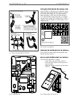
Fig. 5. Options for Wiring Multiple PCD7.LR-TR4x
Fig. 6. Terminal connections.
Each wall module on a Sylk bus must use a different bus address,
and there may be multiple PCD7.LR-TR4x wired on a single Sylk
bus. To change the bus address of a wall module, adjust the
address dipswitches to match that of the desired bus address
(1-15). Use the bus address label, shown in Fig. 7, as a reference.
The default address for both PCD7.LR-TR40 and PCD7.LR-TR42 is 1.
The address on the wall module must match the address in the
configuration tool.
Setting the Wall Module Bus Address Dial
Fig. 7. Bus address settings label.
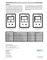
When all wiring is complete, hook the top side, and then snap
down like on a hinge. See Fig. 8.
Attaching the Wall Module to the Subbase
To remove the wall module from its subbase:
1. Locate the two snaps on the bottom of the IFC .
2. Push a screwdriver into each snap to release the IFC
from the subbase.
3. Pull the wall module up and away from the subbase.
See Fig. 8.
Removing the Wall Module from Subbase
Fig. 8. Drilling template (view from above)
TO CONTROLLER
TWO WIRES INTO ONE TERMINAL
DAISY-CHAINING
MULTIPLE PCD7.LR-TR4x
TO CONTROLLER
TO PCD7.LR-TR4x
13 mm
STRIP 13 mm
FROM WIRES
TO BE ATTACHED
AT ONE TERMINAL.
1.
2.
TWIST WIRES
TOGETHER
WITH PLIERS
(A MINIMUM OF
THREE TURNS).
3.
CUT TWISTED END OF WIRES TO
5 MM BEFORE INSERTING INTO
TERMINAL AND TIGHTENING
SCREW. THEN PULL ON EACH WIRE
IN ALL TERMINALS TO CHECK FOR
GOOD MECHANICAL CONNECTION.
WALL MODULE
TERMINALS
HOME RUNNING
MULTIPLE PCD7.LR-TR4x


