Hardware manual PCD1.M2220-C15 │ Document 27-640 – Version ENG03 │ 2020-03-25
Saia-Burgess Controls AG
Introduction
Guidance
2-5
2
2.2.4
Addressing the inputs and outputs (I/O)
Optical starting point for the following description
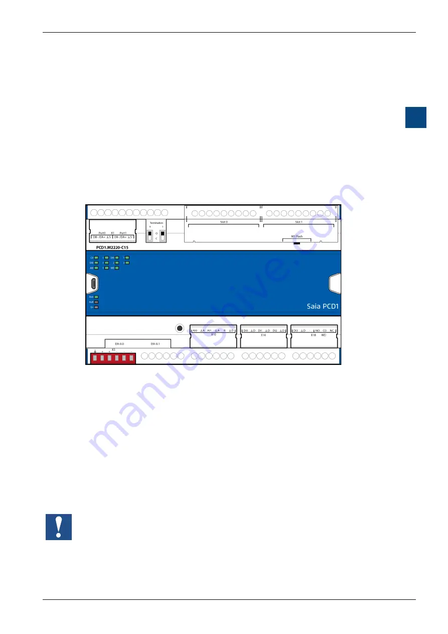
The PCD is mounted as shown below so that the text can be read from left to right.
Addressing
For Saia PCD
®
controllers PCD1.M2220-C15, addressing the IO slots starts from
left to right. The integrated I/Os on the PLC processor boards (on-board) are as-
signed to the terminal blocks X10, X14, X18 and are located on the underside
of the PCD.
Slot 0
X10
X14
X18
Slot 1
Call-up of the inputs and outputs on Slot 0 and Slot 1 for each PG5
Direct access to the IO elements from each PCD2 EA plug-in module takes place
in the program using its media code and address number, separated by a space.
Example: Input 5 “I 5” or output 16 “O 16”. Where the letters “I” and “O” refer to
the media code (element type) and the number is the absolute address.
Further details about programming are included in the help system of the PG5
programming tool or in the relevant manual.
All inputs and outputs on the CPU board (on-board) are assigned with the device
configurator (device configurator in the PG5 tool) by the programmer to flags and
registers (media mapping).


