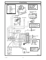
Saunier Duval Xeon 40ff Скачать руководство пользователя страница 28

28

221657C

Diagram 9.2

9 Fault Finding

Is neon 1 lit?

Is neon 2 lit?

Correct power supply problem.

Is there 230V~
between   3    on thermostat and   N   ?

Replace thermostat.

Is neon 3 lit?

Is there 230V~ between
 "N/C"  on air pressure switch and    N   ?

Check yellow cable between printed circuit
board and air pressure switch.
If satisfactory replace printed circuit board.

Is there 230V~ between   "C"   on air
pressure switch and   N   ?

Replace air pressure switch.

Does fan run?

Replace fan.

Replace printed circuit board.

Does fan Hunt?

Inspect air tubes for leaks, kinks and correct
fitting. If satisfactory replace faulty air pressure
switch.

Is there 230V~between   "N/O"   on  air
pressure switch and    N    ?

Isolate supply, test harness continuity.
If satisfactory replace printed circiut board.

Is there 230V~ between pilot
multi-functional control solenoid
blue and brown connections?

Check lead continuity and inspect electrode and
lead for damage.

Is there a spark at pilot burner?

Check for pilot jet blockage, incorrect electrode
adjustment.  If satisfactory replace
multi-functional control.

Does pilot light?

Inspect electrode lead /connection
for poor contact.  Check electrical supply
polarity and correct if necessary.
If satisfactory replace printed circuit board.

With pilot lit does spark stop?

Isolate supply, test harness and replace as required.

Is there 230V~  between main
multi-functional control solenoid black
and blue cables?

YES

Replace multi-functional control.

Is Neon  4 lit?

Does main burner light?

System satisfactory

Is there 230V~ between    SL    and
 N    and between    L     and    N   ?

Is there 230V~ between yellow connection
on overheat device and    N   ?

Is there 230V~ between motor connections on fan?

Isolate electrical supply test fan
harness continuity.
If satisfactory replace printed circuit board.

For gravity domestic hot water systems only,
check continuity of yellow link.  For fully
pumped systems,  check overheat reset.
If satisfactory replace overheat device.

Before detailed checking of electrical components ensure that remote controls are calling for heat.  Check the gas supply is free of obstructions and purged of

air.  Check the overheat cutoff has not operated,  for fully pumped systems only.  Isolate the electrical supply and physically check ALL cables, connections

and the printed circuit board fuse.   Check the air tubes to the air pressure switch.  Switch on the electrical supply and check for correct polarity.  Turn the

boiler thermostat to its maximum setting. Also check fuses.

YES

YES

YES

YES

YES

NO

NO

NO

NO

NO

NO

NO

NO

YES

NO

YES

YES

YES

YES

YES

NO

NO

YES

NO

YES

YES

YES

YES

YES

NO

NO

NO

NO

NO

NO

YES

NO

M A I N   T E R M I N A L   S T R I P

C O N T R O L   T H E R M O S T A T

Содержание Xeon 40ff

Страница 1: ...the Heatcall Customer Service number 01773 828100 Our Guarantee gives you peace of mind plus valuable protection against breakdown by covering the cost of Guarantee Registration Fanned Flue Boiler S I...

Страница 2: ...The Health and Safety at Work Act 1974 we are required to provide information on substances hazardous to health CERAMIC FIBRE INSULATION PADS These can cause irritation to skin eyes and the respirator...

Страница 3: ...electrical supply failure the overheat safety cutoff device may need resetting remove the controls cover and press the reset button refer to diagram 1 Overheat Safety Cutoff If the overheat safety cut...

Страница 4: ...ler being full of water consult your installation servicing company ALL SYSTEMS Turn the electrical supply on to the boiler and check that all remote controls are calling for heat To Turn the Boiler O...

Страница 5: ...The manufacturer s instructions supplied TheGasSafety InstallationandUse Regulations TheBuilding Regulations The Building Standards Scotland Regulations applicable in Scotland Local Water Company Bye...

Страница 6: ...00Table 16 not less than 0 75mm2 24 0 20mm 1 7 Contents of Packaging The boiler is delivered in one pack refer to Section 4 1 for contents 1 8 Water System This boiler may be fitted to an open vented...

Страница 7: ...e in an unusual position special requirements are needed the current issue of BS6798 gives detailed guidance on these requirements A compartment used to enclose the boiler must be designed and constru...

Страница 8: ...to the external air the position allowing free passage of air across it at all times Car ports or similar extensions of a roof only or a roof and one wall requirespecialconsiderationwithrespecttoanyo...

Страница 9: ...be 15mm minimum size It is important that the relative positions of the pump cold feed and open vent are as shown in diagram 3 2 Theunrestrictedopenventfromtheboilermustrisecontinuously to discharge o...

Страница 10: ...LOCKSHIELD VALVE FLOW RET There must always be a cold water path to the return connection of the boiler PUMPED RETURN PUMPED FLOW 4124 Diagram 3 4 1metre Min 27 metres Max 22mm VENT 15mm COLD FEED TO...

Страница 11: ...volume Note A higher initial design pressure requires a larger volume expansion vessel Guidance on vessel sizing is also given in the current issue of BS5449 and BS7074 Part 1 The charge pressure mus...

Страница 12: ...REAKER PRESSURE REDUCING VALVE 0051M Diagram 3 6 3 16 Filling a Sealed Water System Provision for filling the system at low level must be made Three methodsareshownindiagram3 6 Theremustbenopermanent...

Страница 13: ...4 1 Unpacking Open the carton check the items supplied against the boiler pack contents list on the flap and diagram 4 1 4 2 Flue Position and Length Determine flue application length and terminal pos...

Страница 14: ...onalwallliner kit isusedtheflue can be fully installed from the inside For a wall thickness of over 300mm the external flue hole will need to be made good from the outside This applies also if you use...

Страница 15: ...m 4 5 Drill holes and plug to suit No 12x2in wood screws fit the screws allowing sufficient clearance about 5mm to accept the swing brackets see diagram 4 5 Secure the mounting bracket to the wall wit...

Страница 16: ...manifold secure with the two self tapping screws supplied in the loose items pack It should now not be possible to remove the manifold 4 10 Rear Fitting Fit the self adhesive foam seal provided in th...

Страница 17: ...er is not to be fitted for some time cover the hole in the wall On limited access installations push the flue assembly into the hole such that it is within the wall and does not stick out into the roo...

Страница 18: ...e diagram 5 4 Remove the fan assembly by removing the screws at the front slackening the screws at the rear and sliding it out see diagram 5 4 Secure the flue assembly to the boiler using the previous...

Страница 19: ...ng clip from the loose items pack peel off the backing paper and position it in a suitable place to secure the incoming cable Using heat resistant 85o C cable of at least 0 75mm2 24 0 2mm to the curre...

Страница 20: ...ATED VERTICAL REAR RIGHT LEFT SCREW 2 JUBILEE CLIP Cutting MARK lengths Lefthand flue does not require cutting SIDE LEFT FAN DUCT EXTENSION SIDE RIGHT REAR FLUE ELBOW FAN DUCT EXTENSION FAN DUCT EXTEN...

Страница 21: ...ring diagrams for either a sealed water system or fully pumped open vented diagram 5 10 and 9 7 PUMPEDHEATINGANDGRAVITYDOMESTICHOTWATER Make sure that the red link is connected between terminals SL an...

Страница 22: ...is isolated from the electrical supply Makes sure that the control thermostat is turned to O the Off position Turn the gas service cock On see diagram 6 1 Testthepilotsupplytubeanditsconnectionsforgas...

Страница 23: ...ff either by the control thermostat or a remote system control To make sure that the flame supervision device is working correctly the following should be done 1 With the main burner alight turn the g...

Страница 24: ...r Adjust the pump to the system design setting then balance the system Having achieved a satisfactory condition operate the boiler with the bypass fully closed on minimum load normally this will be ce...

Страница 25: ...by a competent person Before servicing turn off the gas and isolate the electrical supply to the boiler After completing a service always test for gas soundness and carry out functional check on contr...

Страница 26: ...4 Main Injector Withthemainburnerremovedthemaininjectorcanbeinspected and cleaned as necessary see diagram 8 5 If removing for cleaning do not use a wire or sharp instrument on the hole Use a little s...

Страница 27: ...nuity polarity short circuit and resistance to earth checks must be repeated using a suitable multimeter Refer to neon indicators An Aid to Fault Finding diagram 9 1 Boiler Fault Finding diagram 9 2 P...

Страница 28: ...rd With pilot lit does spark stop Isolate supply test harness and replace as required Is there 230V between main multi functional control solenoid black and blue cables YES Replace multi functional co...

Страница 29: ...applied Pump Overrun Operation For Fully Pumped System Only The PCB has a timed pump overrun facility The pump should run for several minutes after remote controls have stopped calling for heat Befor...

Страница 30: ...no switch is fitted link will make the circulation pump run constantly F1 F2 or or or p Diagram 9 4 Diagram 9 5 FUSE TYPE F1 F2 F1A SPARK ELECTRODE O H CUTOFF CONTROL STAT FAN AIR PRESSURE SWITCH PIL...

Страница 31: ...tral heating system remote controls and not to control box Yellow link fitted to bridge out the overheat cutoff b g y E N g y K1 K2 ELECTRODE PN 5859 GRAVITY DOMESTIC HOT WATER AND PUMPED CENTRAL HEAT...

Страница 32: ...3 AMP N E N g y br CIRCULATON PUMP L r See Note SL P PN FULLY PUMPED OPEN VENTED OR SEALED WATER SYSTEM 5860 b N b br b MULTI FUNCTIONAL CONTROL br b Remove red link between 9 and SL when fitting a t...

Страница 33: ...of washers in the front of the control box Remove the split pin and withdraw the thermostat phial from its pocket Releasethecapillaryfromthebaseandplasticretaining clip then remove it from the split g...

Страница 34: ...e PCB to the main terminal strip control thermostat and earth connection Release the main terminal strip and plastic label Carefully pull the board away from its supports When refitting refer to wirin...

Страница 35: ...10 8 Solenoid diagram 10 3 Remove the electrical plug from the multifunctional control Remove the securing screw and then the solenoid Assembly 10 9 Main Burner Remove the main burner as Section 8 3...

Страница 36: ...oved the rear insulation can be removed and replaced 10 12 Viewing Window diagram 10 6 Remove the old self adhesive aluminium foil gasket and the old mica window Replace with a new mica window Peel of...

Страница 37: ...sure that the plastic tubes arefittedasshownindiagram10 7andthatelectricalconnections are made as shown in diagrams 9 6 or 9 7 10 14 Fan diagram 5 4 Remove the electrical connections and disconnect th...

Страница 38: ...GC number of the appliance and part Key No Part No Description GC Part No 1 801020 Multifunctional control E25264 2 208040 O ring 334 592 3 205708 Injector 40ff 313 944 4 203431 Pilot burner 379 204...

Страница 39: ...39 221657C Diagram 11 1 5861 1 2 6 4 5 10 9 8 7 11 13 14 15 3 11 Spare Parts...

Страница 40: ...40 221657C Because of our constant endeavour for improvement details may vary slightly from those shown in these instructions...

Отзывы: