


18
4000122704-1
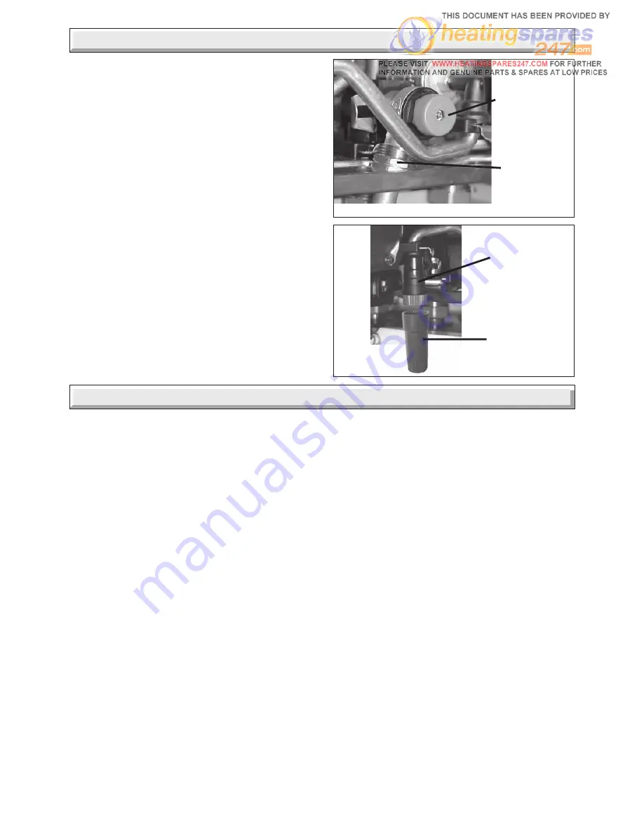
Diagram 9.4
9770
DISCHARGE
SAFETY
VALVE (3 bar)
DISCHARGE
SAFETY
VALVE PIPE
Diagram 9.5
10087
FILLING LOOP
EXTENSION
FILLING
DEVICE
9.4 Discharge safety valve, refer to diagram
9.4.
WARNING. It must not discharge above an entrance or window
or any type of public access area.
A short discharge pipe is supplied in the fittings pack, when fitted
to the safety valve it will end below the boiler. The discharge
pipe must be extended using not less than 15 mm o.d. pipe, to
discharge in a visible position outside the building, facing
downward preferably over a drain.
Note: Fit a compression fitting to facilitate service of the
appliance.
The pipe must have a continuous fall and be routed to a position
so that any discharge of water, possibly boiling or steam, cannot
create any danger to persons, damage to property or external
electrical components and wiring. Tighten all pipe connection
joints.
9.5 Filling loop extension F30E Only
Remove the filling loop extension knob from the fittings kit. Fit
to the filling device on/off knob this is a push fit, see diagram
9.5.
9 Boiler Installation
10 Horizontal Rear Flue Installation
The
Horizontal Rear flue - kit No A20097 is
suitable for installations that require a flue
length from 300 minimum to 930 maximum. If
longer flueing is required extensions and
bends are available, see note below. If a
shorter flue length is required the flue can be
cut to suit, see diagram 10.2 for minimum flue
length.
Important Note:Additional 1 metre extentions, 90
°
and 45
°
bends are available. The maximum extended flue is 3.5m. The
use of flue bends requires the flue lengths to be reduced by 1m.
for 90
°
and 0.5m. for 45
°
.
10.1 Horizontal Rear Flue kit of parts, refer to
diagram 10.1.
10.2 Cutting Rear Flue, refer to diagram 10.2.
Important Notes: After cutting ensure that there are no burrs.
10.3 Installation of Rear Flue assembly
• Fit rubber sealing collar (C) into groove at the outer end of the
flue assembly (A) and (B), see diagram 10.3.
• Fit flue assembly with attached rubber sealing collar into wall
from the outside with rubber sealing collar to the outside. Pull
assembly inwards to bring rubber sealing collar hard up against
external wall. The oposite end must exit the inner wall face by
30mm. see diagram 10.4. (1.)
• Fit the plastic internal flange (H) over the flue, push along the
pipe until engaged against internal wall, see diagram 10.4. (2.)
• Remove the backing from the wrap around self adhesive seal
(E) and carefully fit seal around the back end of the flue and
internal flange thats extending 30mm. from the inner wall face,
see diagram 10.4. (2.)
• Remove the backing from the wrap around self adhesive semi
rounded seal (D) and carefully fit seal around the front end of
the flue thats extending 30mm. from the inner wall face, see
diagram 10.4. (2.)
• Fit the ‘O’ ring (I) into the interface (G), apply a small amount
of silicone grease to the ‘O’ ring when fitting.
• Ease the interface (G) over the seals, see diagrams 10.4 (3.)
and 10.5.
• Important: Ensure that the flue if cut has no burrs that could
damage the ‘O’ ring. If the flue length is less than 500mm. fit the
flue restrictor (a) into the fan outlet, see diagram 10.6.
• Fit the interface sealing gasket (F) to the interface.
Preparing the boiler
• Lift the boiler up and engage boiler upper part onto the hanging
bracket.
• Fit the washers between the boiler pipes and the inlet and
outlet fittings on the fixing jig and connect the various couplings
between the boiler and jig.
Now the boiler is on the wall, slide forward the interface about
20mm. secure it on to the back of the boiler with the two screws
previously removed, see diagram 10.7.
• Engage the fan outlet into the interface, refit the fan, see
diagram 10.8.
F30E Only
F30E shown


