NOTE:
THIS INSTRUCTION
BOOKLET CONTAINS
IMPORTANT
SAFETY INFORMATION.
PLEASE READ AND KEEP FOR
FUTURE REFERENCE.
English pg 1-23
Français pg 24-26
Español pg 27-29
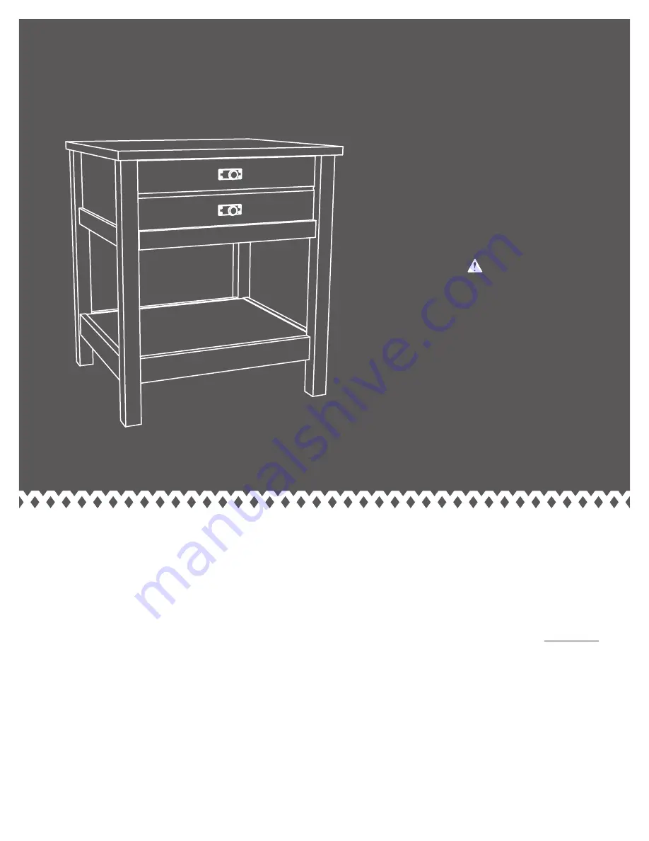
Night Stand
WARNING
CHOKING HAZARD - Small Parts
Not for children under 3 years.
Adult assembly required.


