background image

IntelliFlow 3 Liquid Installation Guide

8

875-3000-100 Rev A1

FLOW METER AND VALVE INSTALLATION

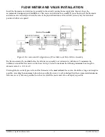
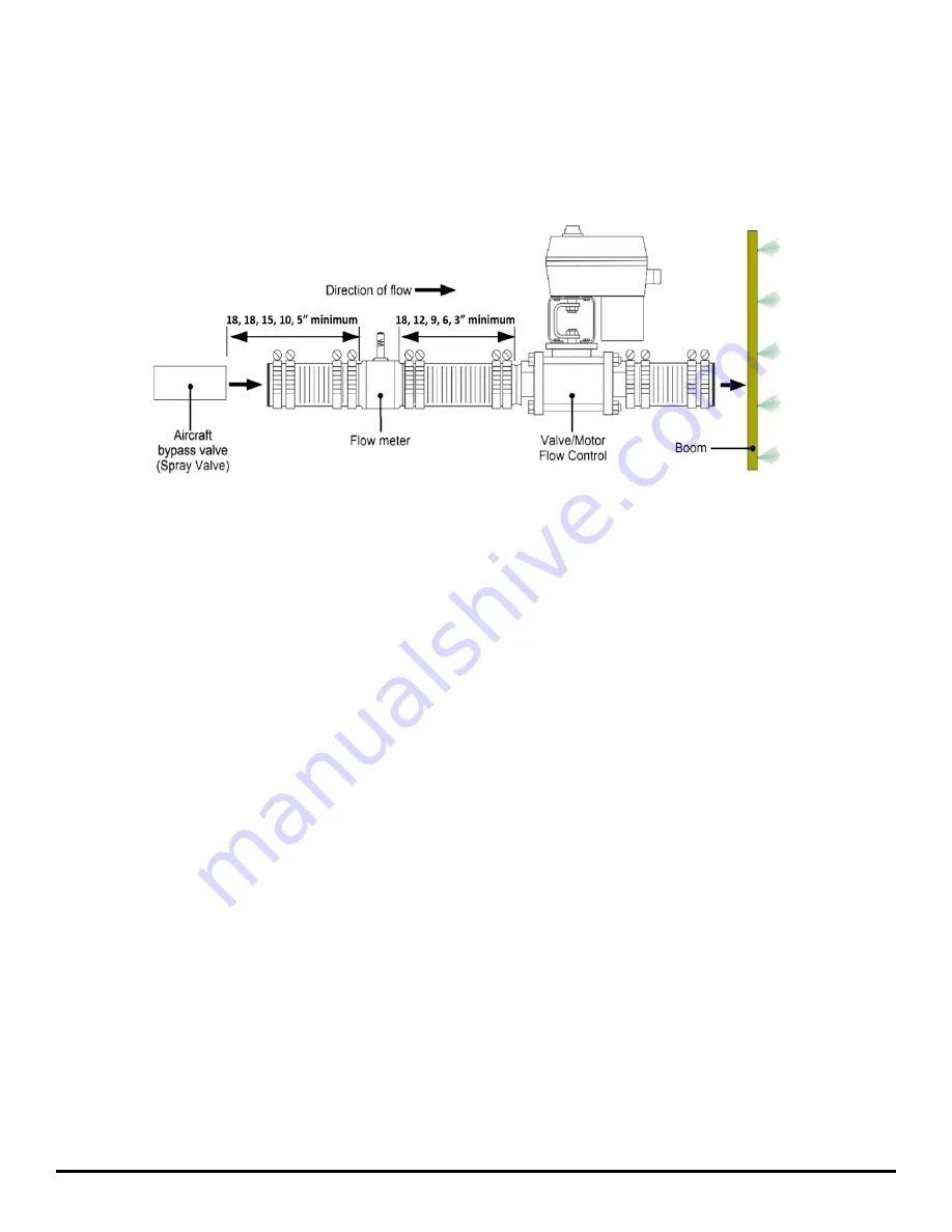
Install the flow meter and valve/motor assembly in the aircraft’s existing boom supply tube. Figure 2 shows the 

recommended configuration of IntelliFlow 3’s flow meter and valve/motor assembly. If you cannot install the flow meter 

and valve/motor vertically (as shown) because of the physical limitations of the aircraft, you may vary the rotational 

position of either as required.

Figure 2: Recommended Configuration of Flow Meter and Valve/Motor Assembly

The flow meter must be installed before the valve/motor assembly to avoid excessive turbulence. To minimize the 

turbulence around the flow meter, cut the hoses (at step 1 below) to maintain the following minimum hose-length to 

diameter ratios (i.e., 10:1 or 6:1). 

The length between the bypass valve and the flowmeter is the 

most critical

; this section should be as long and straight as 

possible, exceeding the minimums below when possible. However, it is acknowledged that the recommended minimum 

distances are very often not possible. In such cases, install the meter and valve as far apart as possible.

Содержание INTELLIFLOW 3

Страница 1: ...This installation guide lists all the parts in the IntelliFlow 3 IF3 liquid kits and provides instructions on how to install the IF3 components associated cables and switches Read this manual thoroug...

Страница 2: ...escription maps PMAPs in the GPS system Fine tune applications through the rate bump feature for more precise applications The Satloc G4 will switch between liquid and dry settings with ease Control y...

Страница 3: ...not allow anyone to operate without instruction For trouble free operation and maintenance of your IF3 system adhere to the following recommendations Avoid using IF3 in extreme environmental condition...

Страница 4: ...750 0046 000 0 5 x1 x1 NPTM 750 0122 000 1 x1 x1 NPTM 750 0091 222 1 5 x2 x 2 Barbed 752 0010 01 1 5 x1 5 x1 5 NPTM 752 0015 01 1 5 x2 x2 NPTM 752 0011 01 2 x2 x2 NPTM 752 0012 01 3 x3 x3 Flange 806 1...

Страница 5: ...0 03 1 or 750 0109 03 2 or 750 0107 03 3 Aviation Hose 1x19 75 of 1 2 or 3 Use between spray valve and meter meter and valve valve and boom Attach with part M 682 1053 222 2 25 or 682 1054 222 2 75 or...

Страница 6: ...e template to mark the fastener hole locations of the four vibration isolator feet Part Pc There are eight holes at 28 drill bit 0 140 iii Drill holes being careful not to cause damage iv Use parts Pd...

Страница 7: ...se hardware from the pre assembled rack mount system to attach horizontal mounting brackets Part O to the CPU ii Use parts Pa and Pb to attach vibration isolators Part Pc to horizontal mounting bracke...

Страница 8: ...red Figure 2 Recommended Configuration of Flow Meter and Valve Motor Assembly The flow meter must be installed before the valve motor assembly to avoid excessive turbulence To minimize the turbulence...

Страница 9: ...ly skin of the aircraft close to the valve and flow meter Do not connect support fittings directly to the flowmeter or valve motor Use stainless wrap around straps and supports Table 4 Minimum Hose Le...

Страница 10: ...IntelliFlow 3 Liquid Installation Guide 10 875 3000 100 Rev A1 Technical Support...

Отзывы: