


Vertical polarized systems
(antenna elements are in vertical position) are often used in
radio systems. In a system between a base station and sub-stations the vertical polarization
is generally recommendable. The antenna of the radio modem can not be mounted on the
same level with the other sub-station antennas in the same building. The best way to
distinguish from the other antennas situated in the neighbourhood is by mounting the
antennas as far as possible from each other on the altitude level. The best result is generally
obtained when all the antennas are in the same mast. With an extra ground plane between
the antennas more distinction can be obtained between the antennas in the mast.
A horizontal polarization
can be used in data transmission between two points. With the
polarization attenuation more distinction is obtained in the vertical polarization interference.
The influence of the directional patterns of the antennas must, however, be taken into
consideration. If a distinction to another interfering antenna is wanted with the horizontal
polarized antennas there must be a good attenuation of the back lobe. In addition to this
the interfering radiator should be situated behind the antenna.
When the system does not demand the use of an omnidirectional antenna it is
recommendable to use directional antennas e.g. two-element yagis in firm external
installations. As the antenna amplification increases the setting of the direction of the
antenna demands for a greater care
.
The base stations in high places should be supplied with 4...6 degree band-pass filters.
Please note that the higher the antenna the larger the broadcast area. The disadvantages
with a too high antenna installation at the base station are that interferences from a larger
area affect the base station and that the base station occupies the channel of a too large
area.
2AS
5 m
RS-232
Data Terminal
30 m
l
o
w loss
cab
le
RS-232
Base Station
Computer
up to 30 km
1 ... n pcs.
1...15 m
Data Terminal
*
*
*
up to 15 km
2AS
2AS
G > 12dBi
G > 6dBi
G > 6dBi
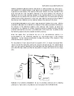
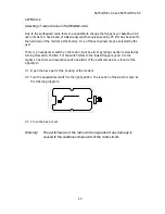
Example of an antenna installation:
By use of amplifying antennas and by installing
antennas in a high location, long distances can be reached with SATELLINE-2AS.
SATELLINE-1AS and SATELLINE-2AS
17


