18
Installer Manual
SATEL
another source of power must be provided for the module (a power supply unit or an
expander with power supply).
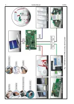
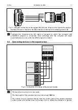
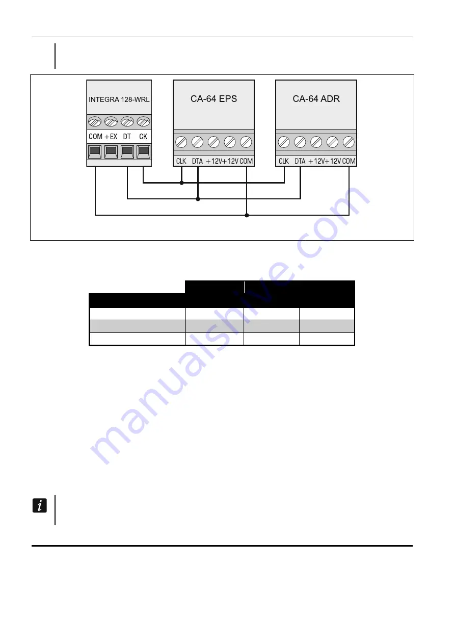
Fig. 7. Connection of modules with power supply.
The Table 3 shows the number of wires required for correct connection of the device to the
expander bus if conductors with 0.5 mm diameter are used.
CK
DT
COM
Distance
Number of wires
up to 300 m
1
1
1
300 – 600 m
2
2
2
600 – 1000 m
2
2
4
Table 3.
5.6.1 Connecting the INT-VG or INT-AV module or CA-64 SM expander
When connecting the INT-VG voice module, INT-AV audio alarm verification module or the
CA-64 SM voice synthesizer expander, the CLK and DTA wires only are to be connected to
the bus. Each of these devices is additionally provided with the PIN5 connector, which is to
be connected to the dedicated socket on the control panel electronics board.
5.6.2 Addressing devices connected to the expander bus
Each device to be connected to the expander bus must have its own individual address from
the 0 to 31 range. The addresses of devices must not repeat (the control panel does not
support devices having identical addresses). It is recommended that consecutive addresses
be assigned starting from 0. In most devices, the address is set by means of DIP-switches.
The address affects numeration of zones and outputs in the system (see section
N
UMERATION OF ZONES AND OUTPUTS IN THE SYSTEM
p. 31).
5.7 Connecting the detectors
How the detector is connected to the zone must be suitable for the configuration chosen for
that zone. The zones on the control panel mainboard support the following configurations:
NC
– the wiring type dedicated to connecting devices with the NC (normally closed) alarm
output. Opening the circuit will trigger an alarm.

