


485
US
Operating Instructions for SATA HRS
Operating Instructions for SATA HRS
vent it from turning.
Attaching a new quick connect coupling
■
Coat quick connect coupling
[2-4]
with Loctite 276.
■
Screw quick connect coupling
[2-4]
onto mixing cap
[2-5]
and tighten.
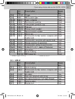
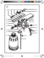
10.2. Replacing the check valve
Removing the check valve
■
Unscrew locking screw
[2-1]
and remove from gun body
[2-6]
.
■
Remove pressure spring
[2-2]
and ball
[2-3]
from gun body.
Installing a new check valve
■
Lubricate pressure spring
[2-2]
and ball
[2-3]
with SATA gun grease
(Art. No. 48173).
■
Insert pressure spring and ball into gun body
[2-6]
.
■
Screw locking screw
[2-1]
into gun body.
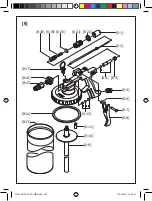
10.3. Replacing the needle seal
Removing the needle seal
■
Unscrew and remove pressure cup
[1-4] / [1-7] / [1-13]
.
■
Unscrew end screw
[3-11]
from gun body
[3-9]
.
Variant with material flow control
■
Unscrew guide bushing
[1-19]
with lock nut
[2-20]
and material flow
control nut
[1-21]
and remove from gun body
[3-9]
.
■
Remove both pressure springs
[3-2]
and
[3-3]
from gun body.
■
Pull paint needle
[3-10]
out of gun body.
■
Use Allen wrench to carefully unscrew and remove pressure screw
[3-4]
from gun body.
■
Remove pressure spring
[3-5]
and seal
[3-6]
from gun body.
Installing a new needle seal
■
Lubricate all moving parts with SATA gun grease (Art. No. 48173).
■
Insert seal
[3-6]
into gun body
[3-9]
with tapered side facing gun body.
■
Insert pressure spring
[3-5]
.
■
Screw on pressure screw
[3-4]
and tighten.
■
Insert paint needle
[3-10]
into gun body.
■
Place both pressure springs
[3-2]
and
[3-3]
on paint needle.
■
Screw end screw
[3-11]
into gun body and tighten.
Variant with material flow control
■
Screw guide bushing
[1-19]
with lock nut
[2-20]
and material flow
control nut
[1-21]
into gun body
[3-9]
.
226704-BAL-SATA HRS.indb 485
17.02.2016 10:48:01


