background image

User’s manual


4


I.


Safety


Before using the device for the first time the user should read the following regulations carefully. Not 
obeying the rules included in this manual may lead to personal injuries or controller damage. The user’s 
manual should be stored in a safe place for further reference. In order to avoid accidents and errors it 
should be ensured that every person using the device has familiarized themselves with the principle of 
operation as well as security functions of the controller. If the device is to be sold or put  in a different 
place, make sure that the user’s manual is there with the device so that any potential user has access to 
essential information about the device.


The manufacturer does not accept responsibility for any injuries or damage resulting from negligence; 
therefore, users are obliged to take the necessary safety measures listed in this manual to protect their 
lives and property. 


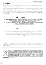
WARNING


High voltage! 

Make sure the regulator is disconnected from the mains before performing any 

activities involving the power supply (plugging cables, installing the device etc.)


The device should be installed by a qualified electrician

.


Before starting the controller, the user shoud measure earthing resistance of the electric motors 

as well as the insulation resistance of the cables.


The regulator should not be operated by children.


WARNING


The device may be damaged if struck by a lightning. Make sure the plug is discon-

nected from the power supply during storm.


Any use other than specified by the manufacturer is forbidden.


Before and during the heating season, the controller should be checked for condition of its ca-

bles. The user should also check if the controller is properly mounted and clean it if dusty or 

dirty.


Changes  in  the  merchandise  described  in  the  manual  may  have  been  introduced  subsequent  to  its 
completion  on  August  25th  2016.  The  manufacturer  retains  the  right  to  introduce  changes  to  the 
structure. The illustrations may include additional equipment. Print technology may result in differences 
in colours shown.. 


We  are  committed  to  protecting  the  environment.  Manufacturing  electronic  devices 
imposes an obligation of providing for environmentally safe disposal of used electronic 
components  and  devices.  Hence,  we  have  been  entered  into  a  register  kept  by  the 
Inspection  For  Environmental  Protection.  The  crossed-out  bin  symbol  on  a  product 
means  that  the  product  may  not  be  disposed  of  to  household  waste  containers. 
Recycling of wastes helps to protect the  environment. The user is obliged to transfer 
their used equipment to a collection point where all electric and electronic components 
will be recycled.


Содержание ST-550 zPID

Страница 1: ......

Страница 2: ...5 c Pre set DHW temperature 12 V 5 d DHW hysteresis 12 V 5 e Temperature of pump activation 12 V 5 f Pre set room temperature 13 V 6 Manual mode 13 V 7 Operation settings 13 V 7 a Feeding time 13 V 7...

Страница 3: ...ion 23 VI 5 b Short circuit pump 23 VI 5 c Floor pump 23 VI 5 d Circulating pump 23 VI 6 Time settings 24 VI 7 Date settings 24 VI 8 Internet module 24 VI 9 Fuel level calibration 27 VI 10 Language 28...

Страница 4: ...istance of the electric motors as well as the insulation resistance of the cables The regulator should not be operated by children WARNING The device may be damaged if struck by a lightning Make sure...

Страница 5: ...certain parameters and control certain functions via the Internet Possibility of controlling two valves via additional modules e g ST 431N Controller equipment CH temperature sensor Feeder temperature...

Страница 6: ...User s manual 6...

Страница 7: ...ST 550 zPID 7...

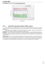
Страница 8: ...les PID control and uses manual settings according to parameters defined in the fitter s menu The display shows the following message PID SUPERVISION IV 3 zPID control ST 550zPID is a controller with...

Страница 9: ...roller is switched on it enters operation mode and OPERATION appears on the display It is the primary mode of controller operation in which the fan operates continuously and the fuel feeder operation...

Страница 10: ...ed if Hall sensor of the fan is active letter H is displayed feeder if burning without feeder option is active a crossed out feeder icon is displayed CH pump DHW pump additional pump 1 additional pump...

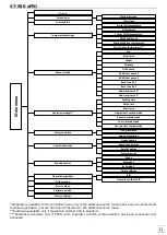
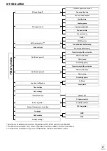
Страница 11: ...set DHW temperature DHW hysteresis Pump activation temperature Pre set room temperature Manual mode Fan Blow force Feeder CH pump DHW pump Additional pump 1 Additional pump 2 Built in valve 1 Built i...

Страница 12: ...set the hysteresis of the pre set temperature It is the difference between the temperature of entering the sustain mode and the temperature of restoring operation mode for example when the pre set te...

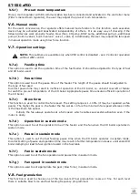
Страница 13: ...ion of the CH boiler i e unburnt coal left or failure to reach the pre set temperature of the CH boiler Appropriate pause time ensures efficient operation of the CH boiler V 7 c Blow force This functi...

Страница 14: ...CH boiler which heats the domestic hot water this value also serves as the pre set water tank temperature After this function has been activated the screen displays current CH temperature and two DHW...

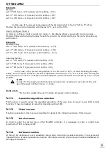
Страница 15: ...iler is 600 C on each weekday Monday Friday from 300 AM to 600 AM the pre set temperature will drop by 100 C so it will be 500 C During the weekend from 4 00 PM to 7 00 PM the pre set temperature of t...

Страница 16: ...s the main screen Once the software update has been completed you can remove the memory stick from the USB port The software update of ST 66P module may be conducted in a similar way by inserting the...

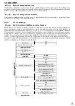
Страница 17: ...n time Fan pause time Fan revolutions Buffer parameters Buffer DHW function Pre set bottom buffer temp Pre set top buffer temp Valve settings Additional pump 1 Operation algorithm selection Short circ...

Страница 18: ...eded by 5 C Once the process is completed the controller constantly monitors the CH boiler temperature If it drops by a pre defined vale the fire up process is initiated again NOTE Damping mode concer...

Страница 19: ...the submenus Valve 1 and Valve 2 are intended for controlling such valves In the case of valves 1 and 2 it is necessary to register in order for the valve to operate correctly To register the valve e...

Страница 20: ...g range differs depending on the valve type The pre set temperature value may be adjusted directly from the main screen view by twisting the pulser knob Valve1 Valve 2 Registration Valve status ON OFF...

Страница 21: ...ve for 4 intermediate external temperatures TEMP FOR 20 C TEMP FOR 10 C TEMP FOR 0 C TEMP FOR 10 C Heating curve it is a curve according to which the pre set controller temperature is determined on th...

Страница 22: ...om temperature see Room temperature difference This function is active only with TECH room regulator and it is closely related to the Room temperature difference parameter Room temperature difference...

Страница 23: ...pump remains active until the temperature drops below the pre set value by hysteresis value If other sensor is to serve as CH sensor it must be selected in CH sensor parameter VI 5 c Floor pump If flo...

Страница 24: ...rature values for both the pumps and the mixing valves It also enables the user to fire up the CH boiler activate CH boiler damping procedure or adjust the operating parameters online The installation...

Страница 25: ...ys the main screen with tiles illustrating the current status of particular heating system devices Tap on the tile to adjust the operation parameters The user may customize the home page by changing t...

Страница 26: ...ller parameters The following tabs include main controller parameters The menu structure is the same as the structure of the main controller menu Screenshot presenting an example tab with main menu Sc...

Страница 27: ...usually performed only once The first step involves filling the fuel tank up and selecting the option Fuel tank full by pressing the pulser knob The controller remembers the level as full 100 When th...

Страница 28: ...ype of regulator is selected in CH pump control or CH boiler control submenu the communication is activated automatically VI 12 External temperature correction External sensor correction should be per...

Страница 29: ...Fuel granulation parameter is no longer available in the main menu and Fuel level calibration option is not available in the fitter s menu In the case of pellet boilers it is possible to remotely init...

Страница 30: ...User s manual 30...

Страница 31: ...a pre defined time from the heater deactivation another fire up attempt follows After two unsuccessful attempts the display informs about the fire up failure When the fire up fails the controller sho...

Страница 32: ...nitiated again g Fire up function If this function is active the damping process is initiated when the pre set room temperatures of the controlled devices have been reached The controlled devices may...

Страница 33: ...he water tank is not sufficiently heated When the pre set temperature of water tank is 55O C whereas the actual CH boiler temperature reaches 62O C so called priority temperature the controller disabl...

Страница 34: ...motors CH pump DHW pump fan feeder and circulating pump No Specification Unit 1 Supply voltage V 230V 50Hz 10 2 Maximum power consumption W 11 3 Ambient temperature O C 5 50 4 Maximum output load of...

Страница 35: ...7 Directive 2014 30 EU of the European Parliament and of the Council of February 26 2014 on the harmonisation of the laws of Member States relating to electromagnetic compatibility EU Journal of Laws...

Страница 36: ...User s manual 36...

Отзывы: