


SARTORIUS PMA 7500...
9
Replacing PCBs
In the case of defects, do not attempt to make any repairs at the component
level, but replace the entire subassembly.
Replacing the Main PCB
Note
:
Before replacing the main PCB, use the service software to read out and store
the scale’s data record, if possible. If this is not possible, order a
pre-programmed PCB, indicating the scale model and serial number.
– Open the scale
– Disconnect the cables that lead to the strain-gauge load cell and the
display head.
– Remove the 3 Phillips screws and remove the old PCB
Important:
Make sure the solder bridges on the new PCB are the same as those on the
old PCB; change the solder bridges on the new PCB if necessary. The menu
access switch on the new PCB must be in the “accessible” position; this is the
position when the switch is moved toward the outer edge of the PCB.
– Follow the above instructions in reverse order to install the new main PCB
– Activate the BPI mode, if necessary (see page 6)
Note:
The scale must now be programmed with its individual data.
The following factors must be checked and, if necessary, adjusted:
– Zero-point offset value
– Linearity
– Span
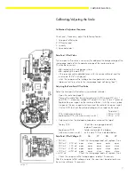
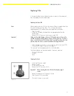
Opening the Scale
– Disconnect the power supply
– Remove the pan
– Put the scale on one side
– Remove the 3 Phillips screws (A, B)
Important!
When removing the screw (A) also the display support
is loose.
– Remove the plactic cover (C) and put it aside.
– Now the main PCB is accessible
– The scale is closed in revers order.
oeffnen-d.TIF
Содержание PMA7500D-X
Страница 2: ......
Страница 15: ...SARTORIUS PMA 7500 15...


