background image

01/31/18

     35            1-800-810-WIRE • www.sargentlock.com • A8205B

Copyright © 2018, Sargen

t Manufacturing Company

, an A

SS

A AB

LO

Y G

roup company

. All right

s reser

ved

Reproductions in whole or in par

t without express writ

ten permission of Sargen

t Manufacturing Company is prohibited

.

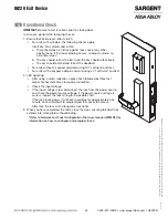
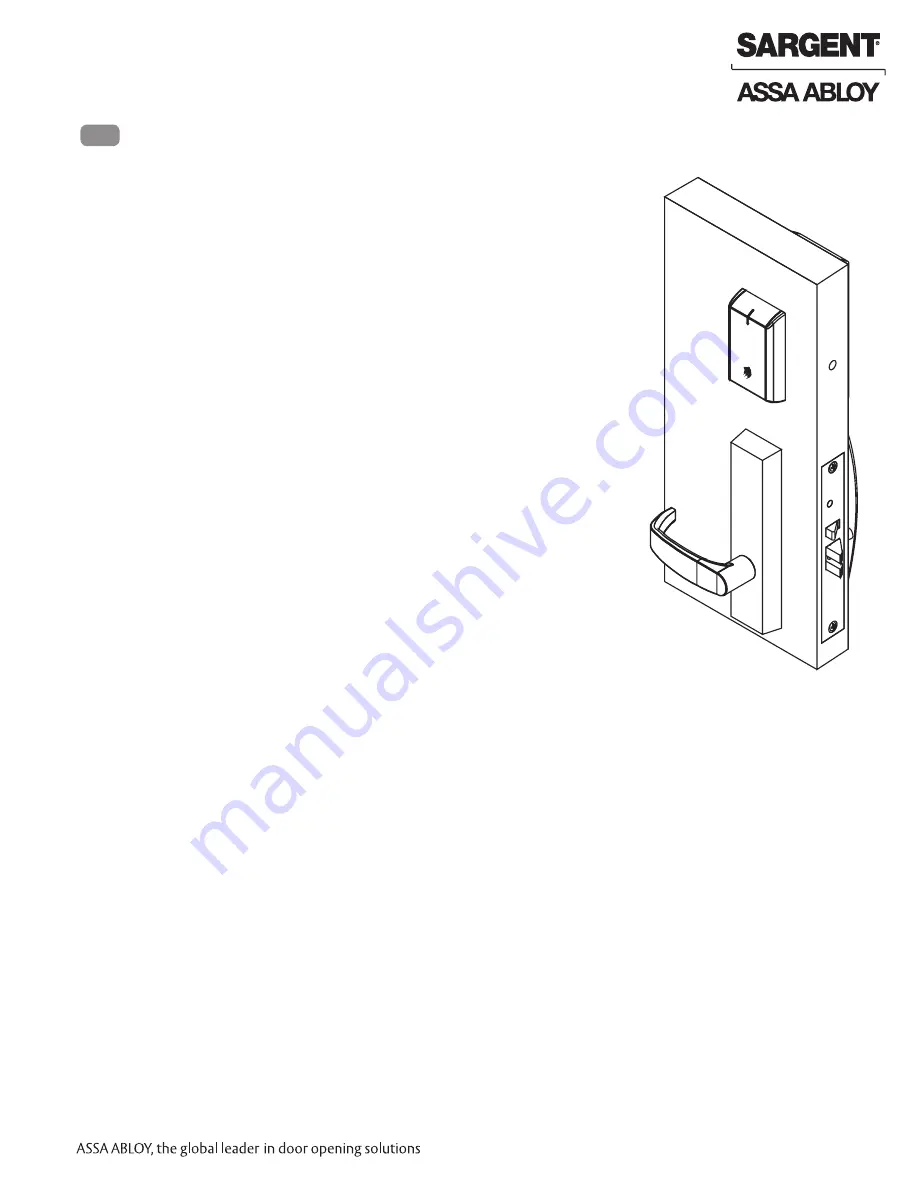
IN220 Exit Device

Operational Check 

9                                                             

IMPORTANT:

 Be sure to test functions prior to closing door.

In all cases, perform the following checks:

1.  Ensure that inside lever retracts latch. 

•  For units with cylinders, the following checks apply:

Insert key into cylinder and rotate:

a.  There should be no friction against lock case or any other  

obstructions. If friction or binding occurs, re-adjust cylinder to  

eliminate issues.

b.  The key should retract the latch and the key should rotate freely.
c.  The key should extend and retract the deadbolt.

•  For units without a keypad, add card using LCT software* and test. 
•  For units with a keypad, add pin and card using LCT software* and test. 

2.  LED signaling:

•  After using a valid credential, a green flash followed by three fast  

amber flashes indicates a low power condition.  

•  Check the input voltage. 
•  If the input voltage is low, disconnect the lock from the power source 

and check the power source voltage. If the power source voltage is  

correct, inspect the lock wiring for a possible short.

       If the lock loses power, it will flash rapid blue for approximately one   

       minute. Lock will default to programmed fail safe or fail secure. 

After that, the lock will no longer be functional.

3.  When you have completed the tests, close the door, ensuring latchbolt fully 

extends into strike plate without binding.

*Refer to Network and Lock Configuration Tool user manual (WFMN1) for 
information on how to configure and program locks. 

Содержание Sargent IN220

Страница 1: ...Manufacturing Company an ASSA ABLOY Group company All rights reserved Reproduction in whole or in part without the express written permission of Sargent Manufacturing Company is prohibited PoE Exit De...

Страница 2: ......

Страница 3: ...gain maximal ou inf rieur approuv pour l metteur par Industrie Canada Dans le but de r duire les risques de brouillage radio lectrique l intention des autres utilisateurs il faut choisir le type d ant...

Страница 4: ...lined architecture of Power over Ethernet PoE access control PoE enabled access control allows facilities to leverage existing network infrastructure for enhanced security and easier more cost effecti...

Страница 5: ...ck plastic IN 220 EM01 B IPS W Reader assembly white plastic IN 220 EM01 B CP B Reader assembly FeliCa black plastic IN 220 EM01 B CP W Reader assembly FeliCa white plastic IN 220 EM01 B CP MB xxx Rea...

Страница 6: ...le Styles 1 3 97 4152 Exit Trim ET With Cylinder 1 97 4153 Exit Trim ET Without Cylinder 68 7546 Motor Actuator Assembly 1 52 5657 Ecoflex ET Harness 1 4 68 7255 Chassis Assembly 1 68 7256 Chassis Ass...

Страница 7: ...rence Catalog for Available Cylinders 1 2 Lever Reference Catalog for Available Styles 1 3 97 4136 Exit Trim ET With Cylinder 1 97 4137 Exit Trim ET Without Cylinder 68 7546 Motor Actuator Assembly 1...

Страница 8: ...g Company is prohibited 01 31 18 IN220 Exit Device Installation Wiring 6 Overview SARGENT IN220 PoE Typical Application LMT Lock Management Tool A PoE frame harness assembly B PoE data hinge from McKi...

Страница 9: ...for Earth Ground in 15 Frame Harness Cable drain wire concealed in shrink tubing Patch Panel Cable Cat 5e or higher 24 AWG RJ45 F Jack Approved Software Certified Integrator CI supplies and terminates...

Страница 10: ...ength 24AWG Stranded Drain Wire for Earth Ground in 15 Frame Harness Cable drain wire concealed in shrink tubing Frame Harness Installation 1 Feed cut end of harness into hole on hinge side through si...

Страница 11: ...t force and do not offset connectors Be sure they are completely seated flush Order of installation may vary Refer to appropriate sections for instructions 1 Prop door open 2 Using the ring terminal c...

Страница 12: ...mended 3 Use appropriate templates IN220 template A8214 wood and metal Exit installation instructions A6770 Note Instruction examples show wood door installation For metal doors route cables inside do...

Страница 13: ...oors have 3 4 raceway to the controller cutout Refer to template A8214 1 Insert connector end of DPS through the raceway on the latch edge of the door Fig 2A Note For metal doors use DPS Collar 2 Push...

Страница 14: ...nd two different sized ground lugs Fig 3A 1 Feed 6 pin connector and larger ground lug straight through to outside of door Fig 3A B while feeding smaller ground lug into wire hole up through wire chan...

Страница 15: ...door surface A Connect motor harness adapter to chassis harness connector Fig 4A B For wood doors Route ET wire harness connector through the cylinder hole up and through the wire run channel to the...

Страница 16: ...Chassis 4 10 Wood Screws or 10 24 Machine Screws Inside of Door 2 12 24 x 1 7 8 Flat Head Screws Through bolts Cylinder to Chassis Fig 6 For devices without cylinder go to Step 6 1 While installing t...

Страница 17: ...y All rights reserved Reproductions in whole or in part without express written permission of Sargent Manufacturing Company is prohibited IN220 Exit Device Secure chassis cover to chassis using 4 8 32...

Страница 18: ...ent Manufacturing Company is prohibited 01 31 18 IN220 Exit Device 8 Outside Reader and Mounting Plate Installation Fig 8A 1 Orient the reader so the LED lens is at the top 2 Feed the cable connector...

Страница 19: ...ock Body Fig 9B Fig 9C 4 Next feed the cables connectors through the inside mounting assembly and gasket if required 5 Insert and partially tighten 2 through bolts prior to installation of connectors...

Страница 20: ...Plate IMPORTANT Do not run wires through bottom hole in plate Fig 10A B it will damage wires and the controller connector Route wires around flange do not route wires through the flange hole Fig 10B C...

Страница 21: ...gnment of board to board connectors while pivoting bottom of controller toward door until tab on bottom snaps securely into place on mounting plate CAUTION To avoid possible damage to board to board c...

Страница 22: ...ithout express written permission of Sargent Manufacturing Company is prohibited 01 31 18 IN220 Exit Device 12 Inside Cover Installation 1 Assemble cover by hooking top edge on inside mounting plate 2...

Страница 23: ...ufacturing Company is prohibited IN220 Exit Device 1 Retrieve harness from end of rail Note Harness has limited travel and can be damaged 2 Attach harness to female connector on chassis 3 Install rail...

Страница 24: ...1 If using a mullion install it prior to installing hardware 2 Doors should be pre prepped recommended 3 Use appropriate templates IN220 template A8215 Field Prep Template Exit installation instructio...

Страница 25: ...have 3 4 raceway to the controller cutout Refer to template A8215 1 Insert connector end of DPS through the raceway on the latch edge of the door Fig 2A Note For metal doors use DPS Collar 2 Push DPS...

Страница 26: ...Fig 3A 1 Slide mortise lock into door and loosely secure with 2 flat head screws NOTE Exit chassis harness consists of a 6 pin female connector and two different sized ground lugs Fig 3A 2 Feed 6 pin...

Страница 27: ...the cylinder hole up and through the wire run channel to the controller cutout For metal doors Route ET wire harness through the cylinder hole out the controller cutout C Pass top ET trim mounting pos...

Страница 28: ...t chassis Note Be sure ET harness is clear of cylinder and tailpiece 2 Secure the cylinder by through bolting the cylinder through the exit chassis using 2 12 24 x 1 7 8 connecting screws see Fig 6A 3...

Страница 29: ...y All rights reserved Reproductions in whole or in part without express written permission of Sargent Manufacturing Company is prohibited IN220 Exit Device Secure chassis cover to chassis using 4 8 32...

Страница 30: ...ent Manufacturing Company is prohibited 01 31 18 IN220 Exit Device 8 Outside Reader and Mounting Plate Installation 1 Orient the reader so the LED lens is at the top 2 Feed the cable connector through...

Страница 31: ...4 Next feed the cables connectors through the inside mounting assembly and gasket if required 5 Insert and partially tighten 2 through bolts prior to installation of connectors NOTE Cable lengths exa...

Страница 32: ...ing Plate IMPORTANT Do not run wires through bottom hole in plate Fig 9A B it will damage wires and the controller connector Route wires around flange do not route wires through the flange hole Fig 9B...

Страница 33: ...ignment of board to board connectors while pivoting bottom of controller toward door until tab on bottom snaps securely into place on mounting plate CAUTION To avoid possible damage to board to board...

Страница 34: ...on 1 Assemble cover by hooking top edge on inside mounting plate 2 Carefully press bottom of cover toward door without pinching wires 3 Secure the cover with the security allen wrench Inside Cover Ins...

Страница 35: ...The key should extend and retract the deadbolt For units without a keypad add card using LCT software and test For units with a keypad add pin and card using LCT software and test 2 LED signaling Aft...

Страница 36: ...uction institutional and industrial markets Copyright 2018 Sargent Manufacturing Company an ASSA ABLOY Group company All rights reserved Reproduction in whole or in part without the express written pe...

Отзывы: