


-
17
-
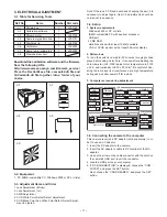
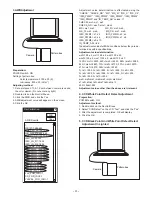
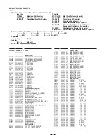
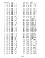
3. ELECTRICAL ADJUSTMENT
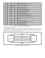
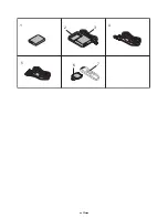
3-1. Table for Servicing Tools
Download the calibration software and the firmware
from the following URL.
http://www.overseas.sanyo.com/dcamera_service/
Place the DscCalDi.exe file, camapi32.dll file and
QrCodeInfo.dll file together into a folder of your
choice.
3-2. Equipment
1. PC (IBM®-compatible PC, Windows 2000 or XP or Vista)
3-3. Adjustment Items and Order
1. Lens Adjustment (Infinity)
2. Lens Adjustment (1m)
3. AWB Adjustment
4. CCD White Point Defect Detect Adjustment
5. CCD Black Point And White Point Defect Detect Adjust-
ment In Lighted
Note: If the lens, CCD and board and changing the part, it is
necessary to adjust again. Item 1-5 adjustments should be
carried out in sequence.
3-4. Setup
1. System requirements
Windows 2000 or XP or Vista
IBM® -compatible PC with pentium processor
USB port
40 MB RAM
Hard disk drive with at least 15 MB available
VGA or SVGA monitor with at least 256-color display
2. Pattern box
Turn on the switch and wait for 30 minutes for aging to take
place before using Color Pure. It is used after adjusting the
chroma meter (VJ8-0192) adjust color temperature to 3100
± 20 K and luminosity to 900 ± 20 cd/m
2
. Be careful of han-
dling the lump and its circumference are high temperature
during use and after power off for a while.
3. Computer screen during adjustment
3-5. Connecting the camera to the computer
This camera requires a DC adaptor (sold separately) in or-
der to use an AC adaptor.
1. Insert the DC adaptor to the camera.
2. Insert the AC adaptor’s cable to DC terminal of the DC
adaptor.
3. Line up the arrow on the cable connector with the notch on
the camera's USB port. Insert the connector.
4. Locate a USB port on your computer.
5. If “USB CONNECTION” is displayed, choose the “COM
PUTER”, and press the SET button.
Next, choose the “CARD READER”, and press the SET
button.
Ref. No.
Name
Part code
J-1
J-2
J-3
J-4
J-5
J-6
J-7
J-8
VJ8-0190
VJ8-0192
VJ8-0191
VJ8-0188
VJ8-0260
VJ8-0282
Pattern box
Calibration software
Chroma meter
Spare lump (pattern box)
Discharge jig
Collimator
Spare lump (collimator)
Siemens star chart
Number
1
1
1
1
1
1
1
1
J-1
J-3
J-4
J-5
J-8
Firmware
Data
AWB
Focus
UV Matrix
R Bright
RGB Offset
Tint
B Bright
Gain
Phase
LCD
Calibration
Upload
PAF Cal.
LCD Type
H AFC
Test
VCOMDC
VCOMPP
Cal Data
Cal Mode
OK
OK
EVF
USB storage
Get
Set
VID
Set
PID
Set
Serial
Set
Rev.
Set
Setting
Language
Video Mode
VCO
Factory Code
Hall Cal.
Backrush pulse :
Set
Get
Содержание VPC-CG11EXG
Страница 11: ... 11 MEMO ...
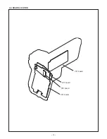
Страница 16: ... 16 2 4 BOARD LOCATION VF1 board ST1 board TB1 board CP1 board ...
Страница 25: ...25 1 5 4 2 3 6 7 ...
Страница 58: ...Aug 09 SANYO Electric Co Ltd Osaka Japan ...
Страница 59: ...SIEMENS STAR CHART ...


