background image

– 2 –

SAFETY PRECAUTIONS

WARNING:

Service should not be attempted by anyone unfamiliar with the necessary precautions for this recording or playback
equipment. The following precautions are necessary during servicing:

1.

Many electrical and mechanical parts in this recorder have
special safety-related characteristics for providing protec-
tion against shock, fire and other hazards. These charac-
teristics often go unnoticed in a visual inspection, and the
protection afforded by them cannot necessarily be ob-
tained by using replacement components with higher rat-
ings (voltage, wattage, etc.).

2.

Replacement parts having special safety-related charac-
teristics are identified in this manual, and in the schematic
diagrams, by the symbol  !  . These components have
values that are of special significance to product safety.
Should any component (identified by the symbol      ) need
to be replaced, use only the part designated in the parts
List. Do not deviate from the specified resistance, wattage,
and voltage ratings.

3.

Before returning the set to the customer, always perform an
AC leakage current check on the exposed metallic parts of
the cabinet, such as terminals, screwheads, metal over-
lays, etc. to be sure that the set is safe to operate without
the danger of electrical shock, Plug the AC line cord directly
into a 120 V AC outlet. (Do not use a line isolation trans-
former during this check.) Use an AC voltmeter with a
sensitivity of 5000 ohms per volt (or more) as follows:
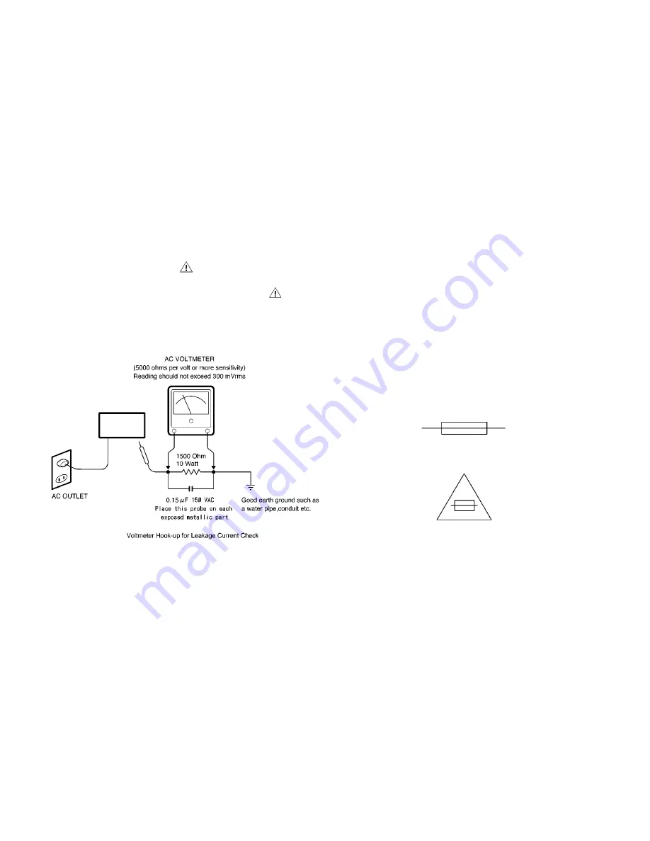
Connect a 1500 ohms, 10 watt resistor, paralleled by a 0.15
mfd, 150 VAC capacitor, between a known good earth
ground (water pipe, conduit, etc.) and the exposed metallic
parts, one at a time. Measure the AC voltage across the
1500 ohms resistor and 0.15 mfd capacitor combination.
Reverse the AC plug at the AC outlet and repeat the AC
voltage measurements for each exposed metallic part. The
measured voltage must not exceed 300 mVrms. This
corresponds to 200 

µ

A AC. Any value exceeding this limit

constitutes a potential shock hazard and must be corrected
immediately.

4.

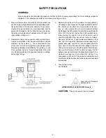
Fuse symbol marks.
For CANADA

UNDERWRITERS LABORATORIES Standard

CAUTION  

"Risk of fire-replace fuse as marked"

For U.S.A.

Fuse rating is marked at
adjacent fuse.

Video

Monitor

Содержание VM-6619A

Страница 1: ...gs 3 Before returning the set to the customer always perform an AC leakage current check on the exposed metallic parts of the cabinet such as terminals screwheads metal over lays etc to be sure that the set is safe to operate without the danger of electrical shock Plug the AC line cord directly into a 120 V AC outlet Do not use a line isolation trans former during this check Use an AC voltmeter wi...

Страница 2: ... control Termination switch Operating environment Power source Power consumption Dimension W x H x D Weight CCIR standard 20 measured diagonally 90 deflection angle More than 1000 TV lines center Horizontal 15 625 kHz CCIR Vertical 50 Hz CCIR Composite video 1 line BNC connector 1 0 V p p 75 ohm negative sync Composite video 1 line BNC connector 1 0 V p p 75 ohm negative sync Composite video 1 lin...

Страница 3: ... 4 Fig 1 W D H Fig 1 DISASSEMBLY 1 1 1 1 1 1 2 1 2 1 METAL TOP COVER ...

Страница 4: ...his socket and to a wall outlet 2 Video input terminals VIDEO IN These terminals are used to input a video signal source to this monitor Connect to the video output of a VCR or an other monitor for loop through connection or to a video camera 3 Video output terminals VIDEO OUT These terminals are used to output a video signal from this monitor Loop through output of the video in BNC connector then...

Страница 5: ... Video B INPUT terminal Video signal cable To Video A INPUT terminal Video signal cable Rear panel To Video input terminal To Video input terminal Monitor Video recorder Fig 3 Monitor Video recorder To Video input terminal Coaxial cable Video camera Fig 5 1 2 3 4 7 6 ...

Страница 6: ...stable hold Adjust VR402 until height for eye comfort obtained Adjust VR901 until D908 voltage to 114V to 115V at 110V AC 113 5V to 114 5V at 120V AC Adjust the vertical linearity control VR401 for equal spaceing of lines between the center extreme of scan The focus control may be adjusted for optimun focus by VR202 The raster is centered by rotating the two small at the rear of the yoke Loosen th...

Страница 7: ...8 7 6 5 4 3 2 1 VR202 FOCUS 2 1 3 4 5 6 7 8 VIDEO BOARD MAIN BOARD VR406 SW901 LED1 VR201 SW202 VR BOARD 11 12 BRIGHTNESS CONTRAST CHANNEL B ADJ H HOLD V LINE V SIZE SUB BRITE D908 Fig 7 Fig 8 MAIN BOARD Foil side VR BOARD Foil side VIDEO BOARD Foil side Fig 9 ...

Отзывы: