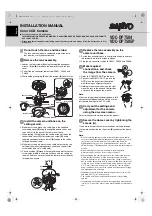


CONNECTIONS
Be sure to attach the supplied clamping core to the cables
as illustrated.
• On the cable for power supply
■
Connection for Alarm Input
Refer to the instruction manual for the connected alarm device
for further details.
■
Connection for Zoom Input
It is used to make wide angle/telescoping adjustments.
■
Setting Color or Black-and-White
You can fix the image either to color or black-and- white using an
external switch, etc.
• Be sure to select “COLOR” for the “DAY/NIGHT” option in the
main menu (See page 23 on the INSTRUCTION MANUAL).
■
Using a Camera Control Unit
When using menus, connect a camera control unit (VAC-70:
Separately ordered) because menu settings can be carried out
without removing the dome cover.
Do not connect the power cord until all other
connections have been completed.
Basic Connection for Monitoring and
Power Supply
To prevent electromagnetic interference
~ ~ GND
+ –
• When using an RG-59U (3C-2V)
cable, do not let it dangle in the air or
attach it to piping.
• If you use a cable other than the types
above, the image or sync signal will be
attenuated and will not be transmitted
correctly.
Cable type
Length
RG-59U (3C-2V)
250 m max.
RG-6U (5C-2V)
500 m max.
RG-11U (7C-2V)
600 m max.
BNC type
AC 24 V connection
DC 12 V connection
Check that polarity is correct.
18 AWG or more
Red
Black
White
Black
Red
Connecting to Other Equipment
Note:
Make sure to disconnect the unit after setting or adjustment is
completed.
External Alarm Input Signal
Alarm device
Purple
Gray
Common
Orange
Gray
Blue
Common
Zoom Input Signal
TELE
WIDE
SYNC
BLC
IRIS
WHITE BALANCE
AGC GAIN
GAMMA
SHUTTER
APERTURE
·DAY/NIGHT
OPTION
PRESET
MENU
INT
OFF
SET y
ATW
NORM
0.45
60
NORM
COLOR
SET y
OFF
END
External switch
Common
Gray
Yellow
Open: Color
Close: B/W
VAC-70
BNC type
RG-6U (5C-2V) cable,
500 m max.
Printed on recycled paper
1AC6P1P3025--
L5BH2/US, XE (0206KP-SY)
Printed in Japan
L5BH2(INSTALL).book 2 ページ 2006年3月1日 水曜日 午前11時41分