

--
Contents
SERVICE MANUAL ........................................................ 1
Contents ........................................................................
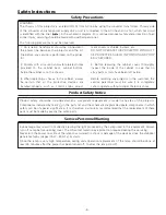
Safety Instructions ......................................................... 3
Safety Precautions ...................................................... 3
Product Safety Notice ................................................. 3
Service Personnel Warning ......................................... 3
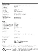
Specifications ................................................................ 4
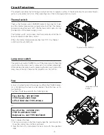
Circuit Protections ......................................................... 5
Thermal switch ........................................................... 5
Lamp cover switch ...................................................... 5
Fuse ............................................................................ 5
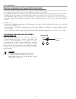
Warning temperature and power failure protection .... 6
Maintenance .................................................................. 7
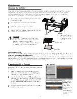
Cleaning the Air Filter ................................................. 7
Resetting the Filter Counter........................................ 7
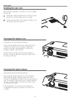
Attaching the Lens Cover ............................................ 8
Cleaning the Projection Lens ...................................... 8
Cleaning the Projector Cabinet ................................... 8
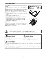
Lamp Replacement ....................................................... 9
Lamp replacement ...................................................... 9
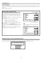
How to check Lamp Used Time ................................ 10
Warning Message on the non-standard lamp used .. 10
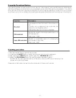
Security Function Notice ..............................................11
Resetting procedure ..................................................11
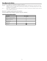
Standby mode Notice .................................................. 1
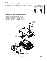
Mechanical Disassembly ............................................. 13
1. Cabinet Top, Front, R/C Board removal .................. 13
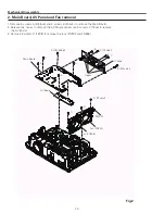
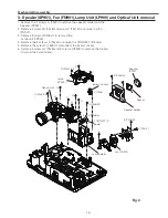
3. Speaker(SP901), Fan (FN901),Lamp Unit(LP900) and
Optical Unit removal ................................................. 15
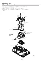
4. Power Board removal ............................................ 16
5. Mounting Duct, Fan(FN903, FN904, FN905) and
Filter Board removal .................................................. 17
Optical Parts Disassembly ........................................... 18
Adjustments ................................................................ 4
Adjustments after Parts Replacement ...................... 4
Optical Adjustments .................................................... 5
Contrast adjustment ................................................. 5
Integrator lens adjustment ....................................... 6
Relay lens-Out adjustment ....................................... 7
Electrical Adjustments ................................................. 8
Service Adjustment Menu Operation ....................... 8
Memory IC (IC1371) Replacement ........................... 8
Circuit Adjustments .................................................. 9
Test Points and Locations ......................................... 34
Service Adjustment Data Table ................................. 35
Chassis Block Diagrams .............................................. 5
Chassis over view ..................................................... 5
System control .......................................................... 53
Lamp control ............................................................. 54
Audio circuit .............................................................. 55
Power supply & protection circuit ............................. 56
Fan control circuit ..................................................... 57
IIC bus Control circuit ............................................... 58
Troubleshooting ........................................................... 59
Indicators and Projector Condition ............................ 59
No Power .................................................................. 60
No Picture ................................................................. 61
No Sound .................................................................. 6
Control Port Functions ................................................. 63
Scaler I/O Port Functions (PW190) ............................ 63
Electrical Parts List ...................................................... 70
Electrical Parts Location ............................................ 71
Electrical Parts List ................................................... 7
Mechanical Parts List ................................................... 91
Cabinet Parts Location .............................................. 91
Optical Parts Location ............................................... 9
Mechanical Parts List ................................................ 96
Diagrams & Drawings ..................................................A1
Parts description and reading in schematic diagram ...A
Schematic Diagrams ....................................................A3
Printed Wiring Board Diagrams.................................. A11
Pin description of diode, transistor and IC .................A15
Note on Soldering ......................................................A16
Содержание PLC-XU300A
Страница 64: ... 64 IC Block Diagrams FA5550NG P F Control IC621 XR16L5701IL24 UART IC9885 ...
Страница 65: ... 65 IC Block Diagrams MAX232ECPWRP RS 232C Driver IC3801 L3E06170 D A S H LCD Driver IC501 IC531 IC561 ...
Страница 68: ... 68 IC Block Diagrams MR4010 Power OSC IC631 PIC18F67J60 LAN CONTROL IC8801 ...
Страница 69: ... 69 IC Block Diagrams FA7703 DC DC Converter IC7811 ...
Страница 97: ...KF5 XU350A00 KA5 XU300A00 97 Mechanical Parts List ...
Страница 98: ... KF5AE KA5AE December 2009 DC 200 Printed in Japan SANYO Electric Co Ltd ...
Страница 108: ...A10 SCH_KF5AE SCH_KA5AE NO DATA ...


