- 2 -
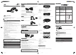
TUNER ADJUSTMENTS
Use a plastic screw driver for adjustments.
Adjust the intermediate frequency of AM and FM to the frequency of ceramic filter.
Set of unit
Supply voltage
:
DC 12.0V
speaker impedance
:
8 ohms
standard output
:
50 mW
Function switch
:
RADIO
a. Parts Location
a.AM Adjustment
Band switch:MW
SG
Position of
VTVM
Input
Output
Frequency
Tuning dial
Oscilloscope
Closed the output
Connect sweep
termial by sweep
generator to
465 KHz
Low
T103
generator,it place
IC101(18) PIN(A)
to MW ANT
2
Connect AM SG to
Connect VTVM to
520 KHz
Low end
T101
Max.
3
test loop
speaker terminals.
1650 KHz
High end
C3
4
Connect AM SG to
Connect VTVM to
600 KHz
600 KHz
MW ANT COIL
Max.
5
test loop
speaker terminals.
1400 KHz
1400 KHz
C4
b.FM Adjustment
Band switch:FM
FM Dummy antenna: 75 ohms unbalance
SG
Position of
VTVM
Input
Output
Frequency
Tuning dial
Oscilloscope
2
Connect FM SG to
Connect VTVM to
87.5 MHz
Low end
L102
Max.
3
FM.ANT & D101(-)
speaker terminals.
108.3 MHz
High end
C1
4
Connect FM SG to
Connect VTVM to
90.0 MHz
90.0 MHz
L101
Max.
5
FM.ANT & D101(-)
speaker terminals.
106.0 MHz
106.0 MHz
C2
Tuning
coverage
Tracking
Adjusting
Circuit
Connections
Adjustment
IF
1
Step
Step
Adjusting
Connection
Adjustment
Circuit
1
IF
Connect sweep
generator to
IC101(24)pin (B)
Connect VTVM to
generator to IC101
(18) pin (A)
10.7 MHz
Low
T102 T104
Tuning
coverage
Tracking
Содержание MCD-UB575M
Страница 6: ... 7 6 EXPLODED VIEW CABINET CHASSIS 74 77 76 75 ...
Страница 9: ... 13 12 This is a basic schematic diagram SCHEMATIC DIAGRAM MAIN ...
Страница 10: ... 15 14 This is a basic schematic diagram SCHEMATIC DIAGRAM CD1 ...
Страница 11: ... 17 16 This is a basic schematic diagram SCHEMATIC DIAGRAM CD2 ...
Страница 12: ... 19 18 WIRING DIAGRAM AUDIO RECTIFIER TUNER WIRING DIAGRAM TUNER CONTROL RECTIFIER USB CONTROL USB ...
Страница 13: ... 21 20 WIRING DIAGRAM CD ...
Страница 14: ... 23 22 WIRING DIAGRAM STDS RECORDING SANYO Electric Co Ltd Osaka Japan Sep 06 BB Printed in Japan ...


