


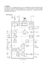
3
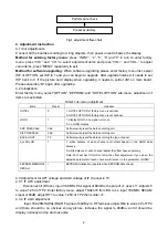
Alignment instructions
1. Test equipment
PM5518 (video signal generator)
VG-848 (VGA, HDMI signal generator)
VG-849 (digital video signal generator)
CA210 (color analyzer)
2. Power test
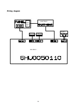
Connect main board, power board and IR board according the wiring diagram, connect the power
and press “standby” to turn on the TV.
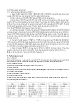
Test the pin voltage of XS15, the data is shown in table1:
Table1 voltage data of XS15
Pin1 Pin2 Pin3 Pin4
Pin5
Pin6
Pin7 Pin8 Pin9 Pin10 Pin11
LC-26HUXX 8.55-9.45V 0
4.75-5.5V 0 11.69-12.92V 0
4.75-5.5V 0
H
LC-32HUXX 8.55-9.45V 0
4.85-5.36V 0 11.4-12.6V 0
4.85-5.36V
0 H
Test the pin voltage of XS16, the data is shown in table2:
Table2 voltage data of XS16
Pin1 Pin2 Pin3 Pin4 Pin5 Pin6
LC-26HUXX 0
4.75-5.5V
0
8.55-9.45V 0
30.4-33.6V
LC-32HUXX 0
4.85-5.36V 0
8.55-9.45V 0
31.36-32.64V
Test the pin voltage of XS11, the data is shown in table3:
Table3 voltage data of XS11
Pin1 Pin2 Pin3 Pin4 Pin5
LC-26HUXX 20.25-23.63V
0
LC-32HUXX 22.8-25.2V
0
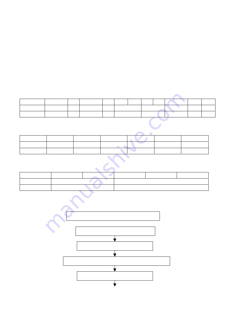
3. Alignment flow-chart
The alignment flow-chart is shown as fig-1
Check DDC, FLASH, HDCP and power control IC
Factory initialization setup
IF channel voltage of TV and AGC voltage adjustment
White balance adjustment
Combined test for general assembly
Содержание LCD-22XR7S
Страница 1: ......
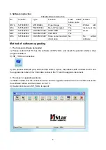
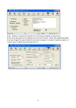
Страница 10: ...8 6 Select the document then the window will appear as shown below Select ...
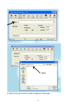
Страница 11: ...9 7 Press Auto to select the writing function ...
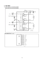
Страница 17: ...15 2 TDA7266SA The TDA7266SA is a dual bridge amplifier ...
Страница 19: ...17 ...
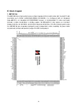
Страница 20: ...18 Wiring diagram main board power board speaker key board IR board pin pin pin pin pin back light ...
Страница 26: ...main board ...
Страница 27: ...main board ...
Страница 28: ...main board ...
Страница 29: ...main board ...
Страница 30: ...main board ...
Страница 31: ......
Страница 32: ...back light board ...
Страница 34: ...APPENDIX B Exploded view LCD 22XR7S ...
Страница 37: ......


